L08 · MIPS R10000
Topic: out-of-order · 39 pages
EECS 4340 Lecture 8 — MIPS R10000
Announcements
Show slide text
Announcements
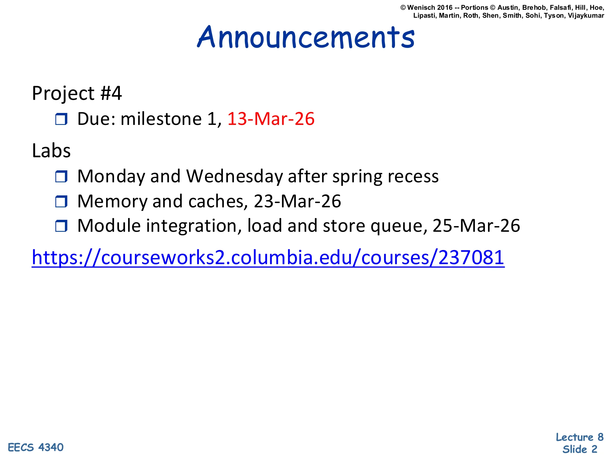
- Project #4
- Due: milestone 1, 13-Mar-26
- Labs
- Monday and Wednesday after spring recess
- Memory and caches, 23-Mar-26
- Module integration, load and store queue, 25-Mar-26
Readings

Show slide text
Readings
For today:
- The MIPS R10000 Superscalar Microprocessor, https://ieeexplore.ieee.org/abstract/document/491460
Recap: P6 Microarchitecture
P6
Show slide text
P6
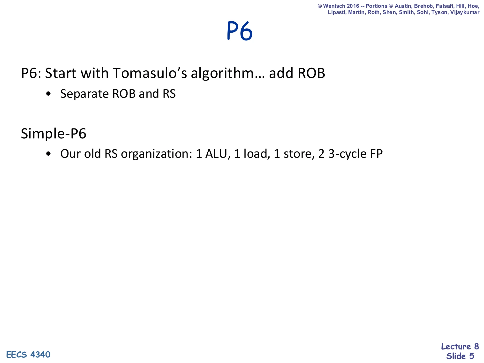
P6: Start with Tomasulo’s algorithm… add ROB
- Separate ROB and RS
Simple-P6
- Our old RS organization: 1 ALU, 1 load, 1 store, 2 3-cycle FP
P6 is the recap baseline for L08. The slide names the recipe for Intel’s PentiumPro family: take Tomasulo’s algorithm (reservation stations + tag-matched wakeup over a CDB) and bolt on a reorder buffer so that completed instructions retire in program order. The key structural decision is that the ROB and the reservation stations are separate arrays with different lifetimes — an instruction allocates an RS entry at dispatch, frees it as soon as it issues to the FU, and only frees its ROB entry at retire. The “Simple-P6” line refers to the canonical RS organization used in the lecture’s running examples: a single integer ALU station, a single load station, a single store station, and two 3-cycle FP stations. Everything that follows on slides 6–11 takes this RS shape and the ROB-with-values design as the starting point against which R10K will be compared. The point of starting here is to make the contrast on the upcoming “Problem with P6” slide concrete: this design works correctly but moves values through too many tables, which is exactly what the R10K design will fix.
P6 Data Structures
Show slide text
P6 Data Structures
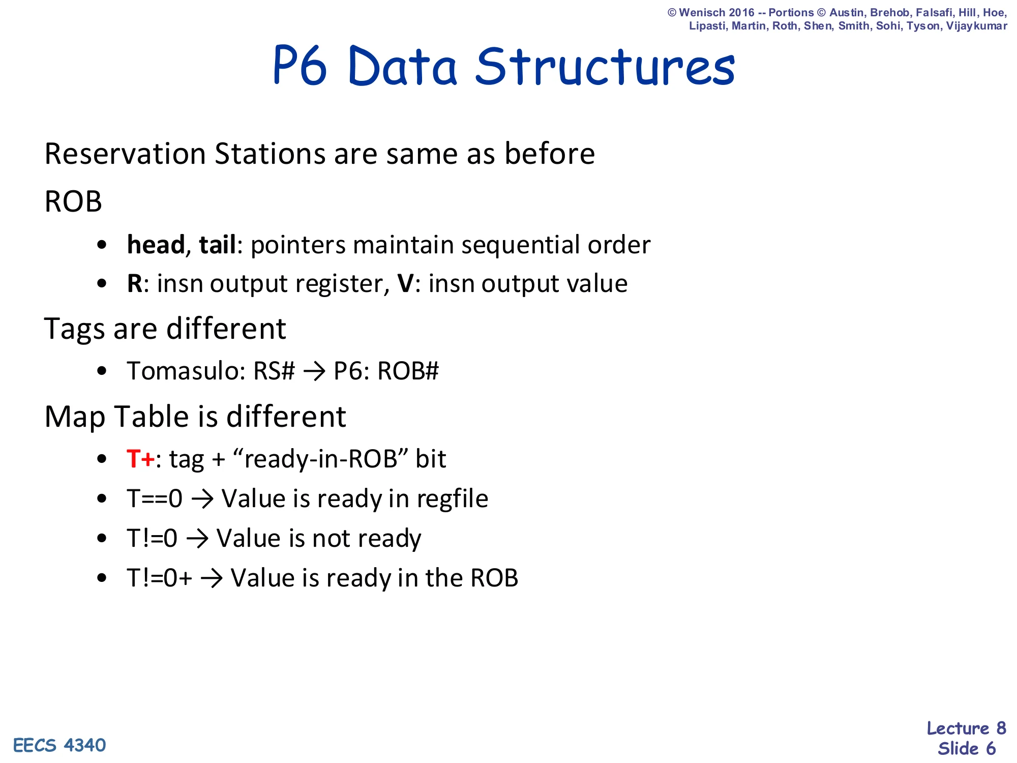
Reservation Stations are same as before
ROB
- head, tail: pointers maintain sequential order
- R: insn output register, V: insn output value
Tags are different
- Tomasulo: RS# → P6: ROB#
Map Table is different
- T+: tag + “ready-in-ROB” bit
- T==0 → Value is ready in regfile
- T!=0 → Value is not ready
- T!=0+ → Value is ready in the ROB
This slide enumerates the three tables that P6 keeps live and how each one differs from plain Tomasulo. The reservation stations themselves are unchanged: each entry holds an op, its destination tag, two source tags, and (when ready) two source values. The ROB is the new structure — a circular FIFO whose head/tail pointers preserve program order, and whose R/V fields hold the architectural destination register name and the speculative output value of each in-flight instruction. The most important change is the tag space: in Tomasulo a producer’s tag was its reservation-station number, but in P6 a producer’s tag is its ROB index, because the ROB (not the RS) is now the home of the speculative value. The map table changes accordingly: each architectural register stores a T+ field that is the producer’s ROB tag plus a single “ready-in-ROB” bit. Three encodings are possible — T==0 means the architectural value is committed and lives in the regfile; T!=0 means a producer is still in flight; T!=0+ means the producer has finished but has not yet retired, so the value is sitting in the ROB ready to be read.
P6 Data Structures (diagram)
Show slide text
P6 Data Structures
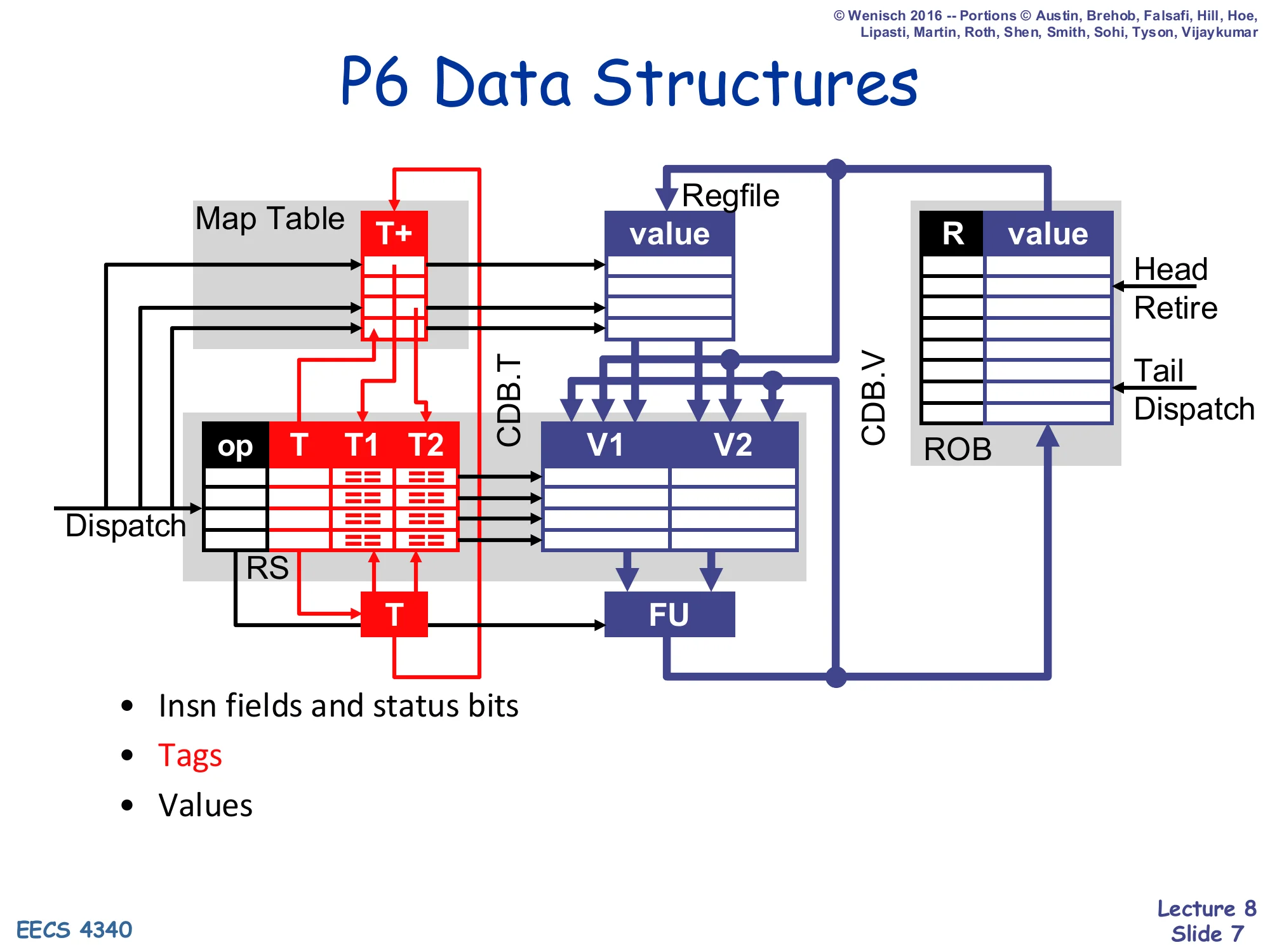
Diagram of dataflow between Map Table (T+), Reservation Stations (op, T, T1, T2, V1, V2), Regfile, ROB (R, value), Functional Unit (FU), and the Common Data Bus split into CDB.T (tag) and CDB.V (value). Dispatch writes the Map Table and RS; the ROB is appended at the Tail and drained at the Head (Retire).
- Insn fields and status bits
- Tags
- Values
The diagram on this slide shows where each kind of bit travels in P6 and is the visual that the “Problem with P6” slide later attacks. Color-coding splits the structures into three concerns. Insn fields and status bits are the black wires: dispatch hands an opcode to the RS and an entry to the ROB, and the ROB tracks completion bits per entry. Tags are the red wires: the map table emits T+ tags for the source operands of a dispatching instruction (read into the RS as T1/T2); the FU broadcasts its own T on the CDB (CDB.T), which is snooped by every RS entry and by the map table to mark values “ready in ROB.” Values are the blue wires: source operands flow regfile/ROB → RS (V1, V2) at dispatch; the FU result flows out on CDB.V to the ROB; finally at retire the ROB pushes the committed value back into the regfile. That “regfile/ROB → RS → ROB → regfile” loop is exactly the value-movement path that the R10K design will collapse by keeping values in a single physical renaming register file.
P6 Data Structures (initial state)
Show slide text
P6 Data Structures
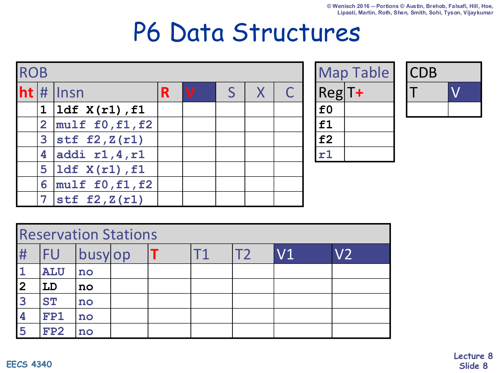
ROB (ht, #, Insn, R, V, S, X, C):
| # | Insn |
|---|---|
| 1 | ldf X(r1),f1 |
| 2 | mulf f0,f1,f2 |
| 3 | stf f2,Z(r1) |
| 4 | addi r1,4,r1 |
| 5 | ldf X(r1),f1 |
| 6 | mulf f0,f1,f2 |
| 7 | stf f2,Z(r1) |
Map Table: rows for f0, f1, f2, r1 (column T+).
CDB: columns T, V.
Reservation Stations (#, FU, busy, op, T, T1, T2, V1, V2):
| # | FU | busy |
|---|---|---|
| 1 | ALU | no |
| 2 | LD | no |
| 3 | ST | no |
| 4 | FP1 | no |
| 5 | FP2 | no |
This is the initial-state snapshot for the P6 walk-through. The seven-instruction loop body — load f1 from X(r1), multiply it into f2, store f2 to Z(r1), increment r1, then repeat — is the same trace that gets re-used on the R10K side starting at slide 24, which is what makes the P6→R10K comparison apples-to-apples. Two columns deserve attention. The R field of the ROB will hold the architectural destination of each instruction (e.g. f1 for ROB#1) so that retire knows which regfile slot to write; the V column will hold the speculative value once execution finishes. On the RS side the Simple-P6 functional-unit mix from slide 5 is realized: one ALU, one load, one store, and two 3-cycle FP units (FP1 and FP2). All busy bits are no because no instruction has dispatched yet — every subsequent slide in this section will fill in entries from the top down as cycles advance.
P6 Performance
Show slide text
P6 Performance
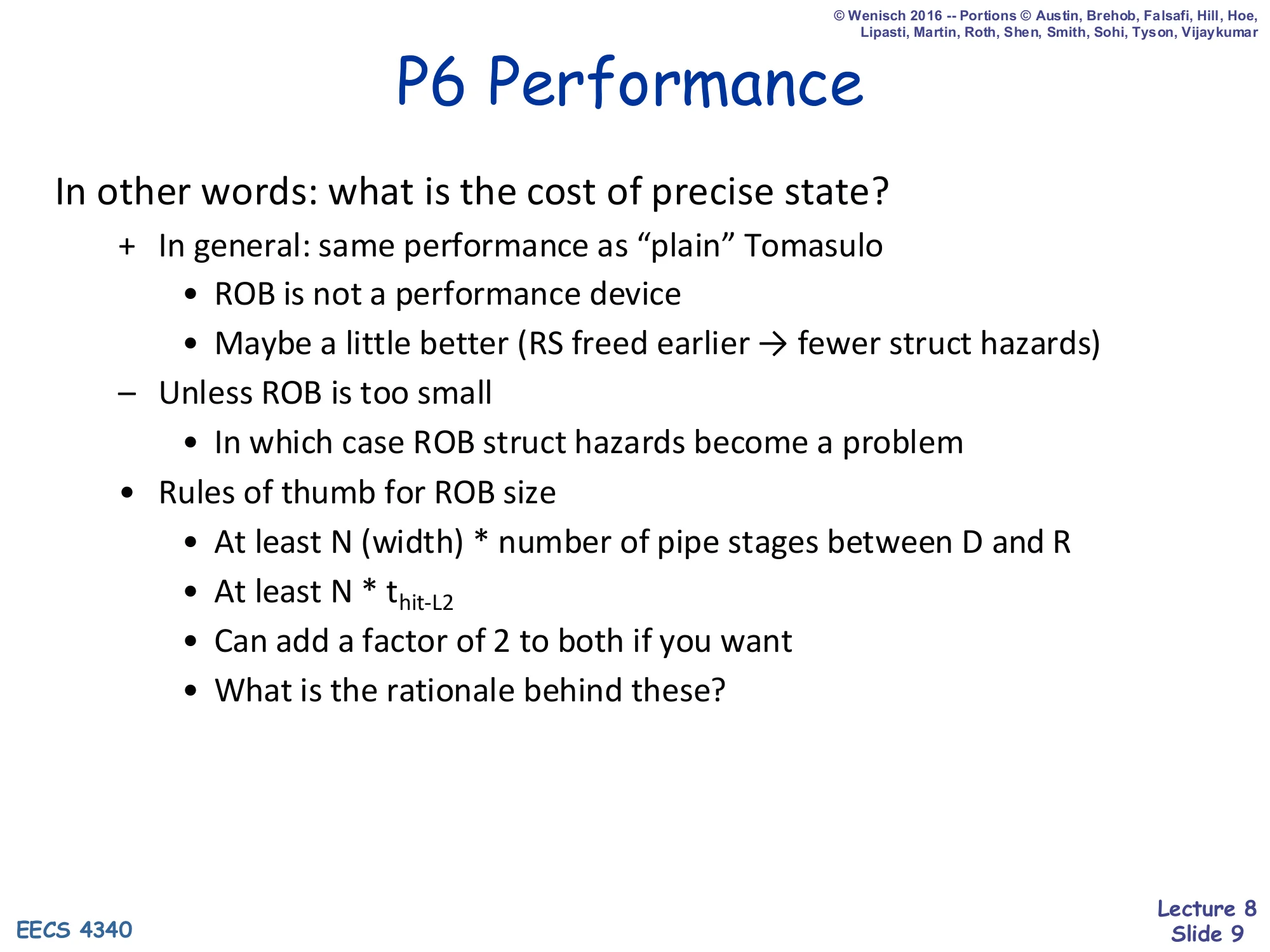
In other words: what is the cost of precise state?
- In general: same performance as “plain” Tomasulo
- ROB is not a performance device
- Maybe a little better (RS freed earlier → fewer struct hazards)
- Unless ROB is too small
- In which case ROB struct hazards become a problem
- Rules of thumb for ROB size
- At least N (width) * number of pipe stages between D and R
- At least N * thit-L2
- Can add a factor of 2 to both if you want
- What is the rationale behind these?
The headline of this slide is that adding a ROB for precise state costs essentially zero performance compared to plain Tomasulo. A ROB is a correctness device — it serializes commit so that exceptions and mispredictions can be cleaned up — and it does not on its own widen issue or shorten critical paths. In fact P6 can run slightly better than vanilla Tomasulo because the RS is freed at issue (rather than at writeback), shaving off some structural-hazard stalls. The catch is sizing: if the ROB is too small, instructions can’t be dispatched even when RSes are free, and the ROB itself becomes the bottleneck. The two rules of thumb both say the ROB must be big enough to hide the latency it sits in front of: N×depth(D→R) keeps the front-end and back-end balanced for an N-wide pipeline, and N×thit-L2 keeps the machine from stalling on a single L2-hit miss. Doubling either is a safety margin for variance and bursty workloads.
P6 (Tomasulo+ROB) Redux
Show slide text
P6 (Tomasulo+ROB) Redux
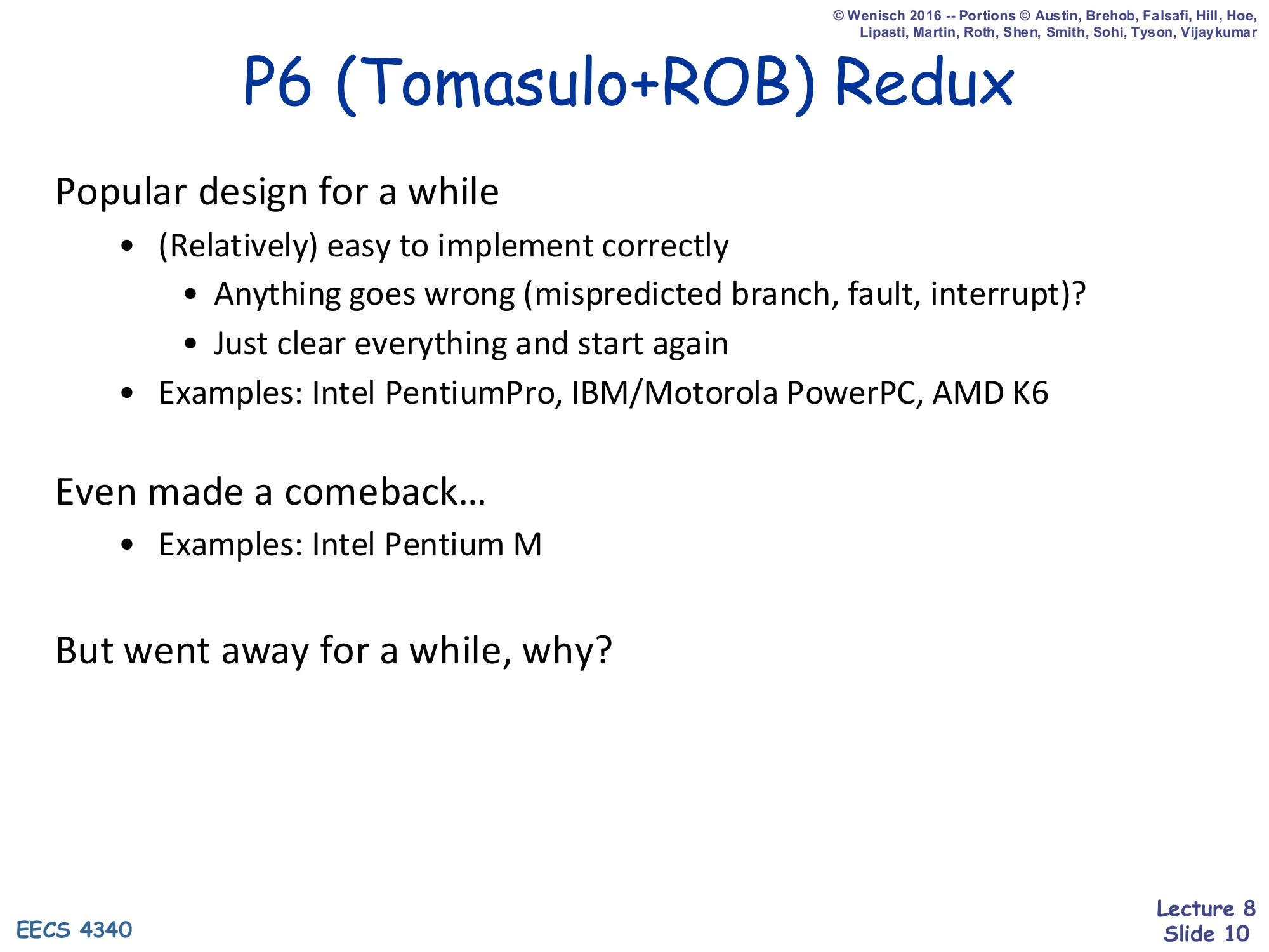
Popular design for a while
- (Relatively) easy to implement correctly
- Anything goes wrong (mispredicted branch, fault, interrupt)?
- Just clear everything and start again
- Examples: Intel PentiumPro, IBM/Motorola PowerPC, AMD K6
Even made a comeback…
- Examples: Intel Pentium M
But went away for a while, why?
This slide places P6 historically. The big selling point is recovery simplicity: because every speculative value lives inside its ROB entry rather than overwriting an architectural register, anything that goes wrong — a mispredicted branch, an exception, an external interrupt — can be repaired by simply flushing the ROB and restarting fetch from the correct PC. There is no need to roll back the architectural register file because no architectural register has been modified yet. That’s why first-generation OoO machines (Intel PentiumPro, IBM/Motorola PowerPC, AMD K6) all converged on this style. The slide foreshadows the rest of L08 with two questions. “Why did it go away?” — because the data-movement bandwidth (regfile/ROB → RS → ROB → regfile, slide 11) became a clock-frequency limiter once designers wanted GHz-class chips, prompting the R10K-style physical-register-file design. “Why did it come back?” — because once frequency scaling stalled and power became dominant, P6’s simpler recovery and lack of a giant CAM-heavy physical regfile became attractive again (e.g. Pentium M).
The Problem with P6
Show slide text
The Problem with P6
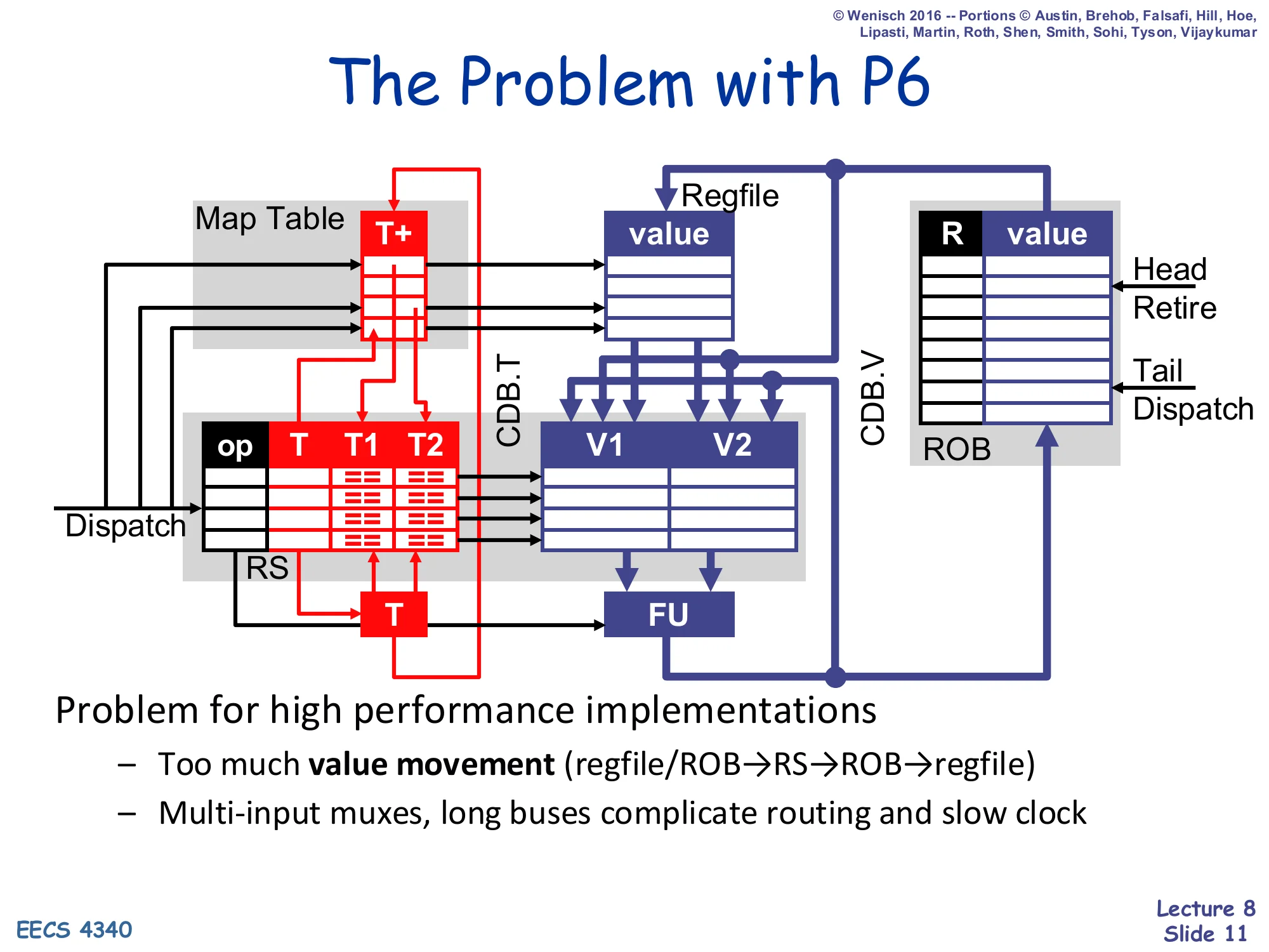
Diagram of P6 datapath: Map Table (T+) → RS (op, T, T1, T2, V1, V2) → FU; Regfile and ROB (R, value) feed values into RS at dispatch; CDB.T and CDB.V broadcast result tags and values back into the RS, ROB, and Map Table.
Problem for high performance implementations
- Too much value movement (regfile/ROB → RS → ROB → regfile)
- Multi-input muxes, long buses complicate routing and slow clock
This slide sets up the entire R10K motivation. P6 stores the same speculative value in three different places over its lifetime — first the architectural regfile or a producer’s ROB entry (read at dispatch), then the consumer RS entry’s V1/V2 field (until issue), then back into the consumer’s own ROB entry (until retire), and finally into the regfile at retire. Every one of those hops is a wide datapath that has to be muxed, routed, and timed. The result is a clock-period problem: the wires between the regfile, ROB, RSes, and FUs are physically long, the muxes selecting between regfile, ROB, and CDB sources are wide, and the bypassing networks become the chip’s critical path. For a designer trying to push to high frequencies, the bottleneck is no longer logic but interconnect. The R10K design (next slides) attacks this directly: keep values in one place — a unified physical register file — and let the RS, ROB, and CDB carry only tags and control bits.
MIPS R10K Microarchitecture
MIPS R10K: Alternative Implementation
Show slide text
MIPS R10K: Alternative Implementation
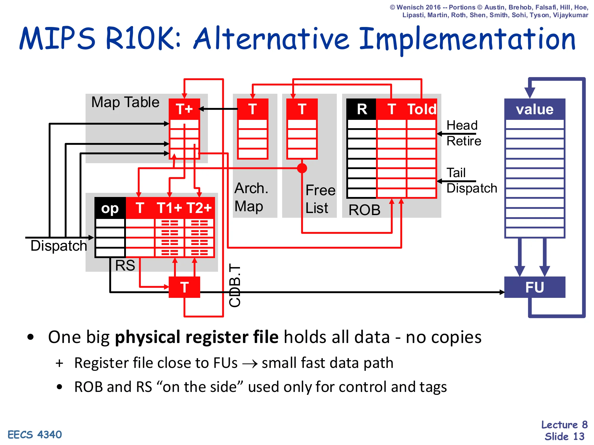
Diagram: Map Table (T+) → RS (op, T, T1+, T2+) feeds tags only; new structures Arch. Map and Free List sit alongside the ROB (R, T, Told); a single physical-register value array sits next to the FU. CDB.T carries only tags.
- One big physical register file holds all data - no copies
- Register file close to FUs → small fast data path
- ROB and RS “on the side” used only for control and tags
The R10K diagram is structurally similar to P6 with three big differences. First, all values live in one place — a unified physical register file — instead of being copied between the architectural regfile, the ROB, and the RS. Second, the ROB no longer has a value column; it now holds two tag fields, T (the physical register allocated to this instruction’s destination) and Told (the physical register that was mapped to this destination before dispatch — needed for register freeing and rollback). Third, two new structures appear: the Arch. Map (a committed-state snapshot of the renaming map table, updated only at retire) and the Free List (a queue of currently-unallocated physical registers). The CDB now carries only T, never values, because values are written directly into the physical register file when the FU finishes. The architectural payoff of these changes is exactly what the slide says — “register file close to FUs → small fast data path,” which removes the clock-frequency bottleneck that motivated the redesign in the first place.
Register Renaming in R10K
Show slide text
Register Renaming in R10K
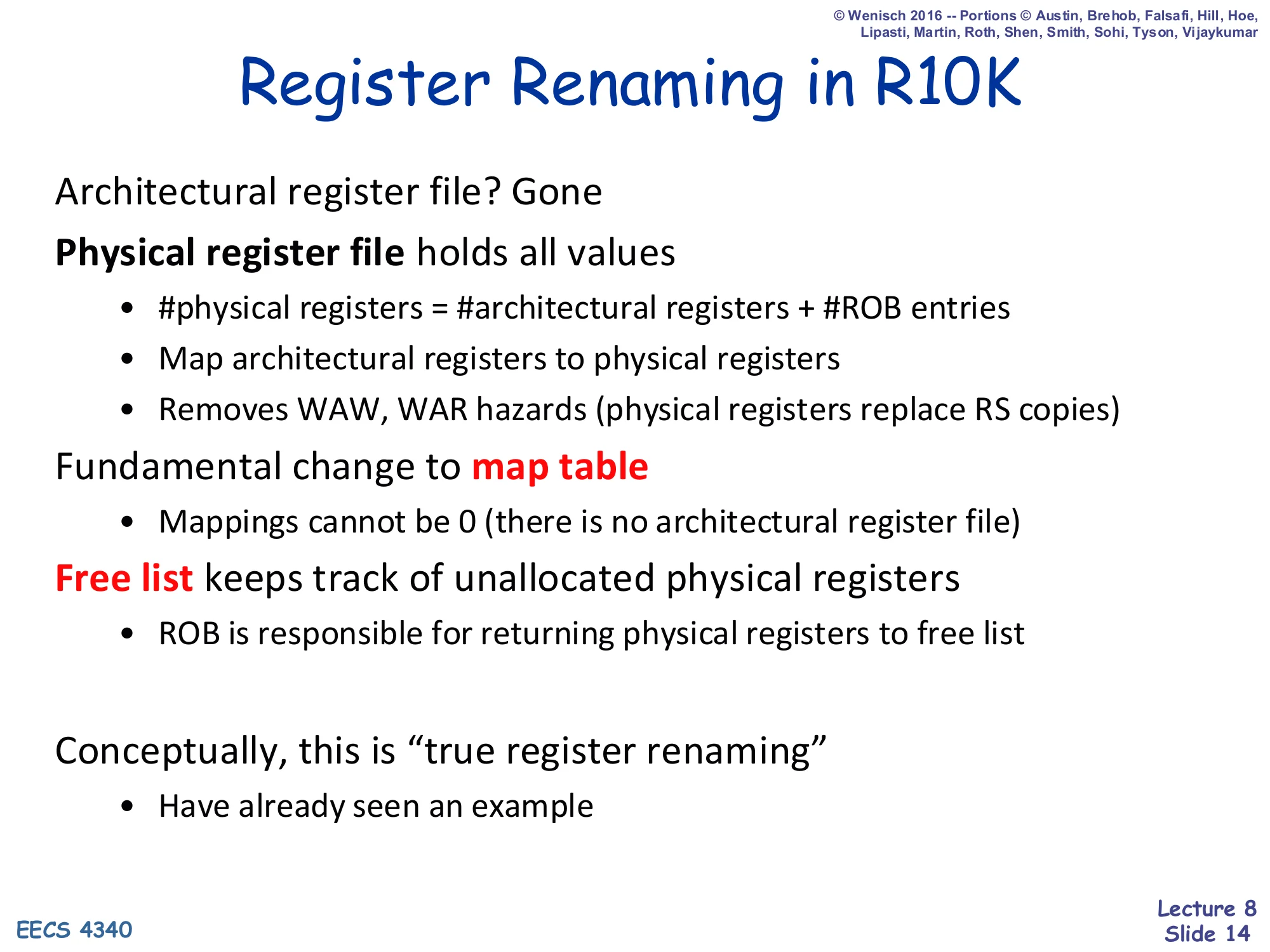
Architectural register file? Gone
Physical register file holds all values
- #physical registers = #architectural registers + #ROB entries
- Map architectural registers to physical registers
- Removes WAW, WAR hazards (physical registers replace RS copies)
Fundamental change to map table
- Mappings cannot be 0 (there is no architectural register file)
Free list keeps track of unallocated physical registers
- ROB is responsible for returning physical registers to free list
Conceptually, this is “true register renaming”
- Have already seen an example
This is the conceptual heart of the R10K. The architectural register file is gone — there is no separate place where committed register values live. Instead, the chip has a single physical register file with at least #architectural + #ROB entries (enough to hold every committed value plus every in-flight speculative value simultaneously). Architectural register names are no longer storage locations; they are just keys into the map table that says “the current producer of r3 is physical register p17.” Because each new write to an architectural register allocates a new physical register from the renaming free list, two writes to the same architectural name end up in physically different storage — eliminating WAW and WAR hazards by construction (and incidentally making the RS-side V1/V2 value copies of P6 unnecessary). Two consequences flow from “there is no architectural register file.” First, every map-table entry must always point to some physical register — there is no T==0 “value is in regfile” encoding any more. Second, freeing physical registers becomes the ROB’s job: it must figure out, at retire, when a physical register’s value is no longer needed by any in-flight instruction, and only then return it to the free list.
Register Renaming Example
Show slide text
Register Renaming Example
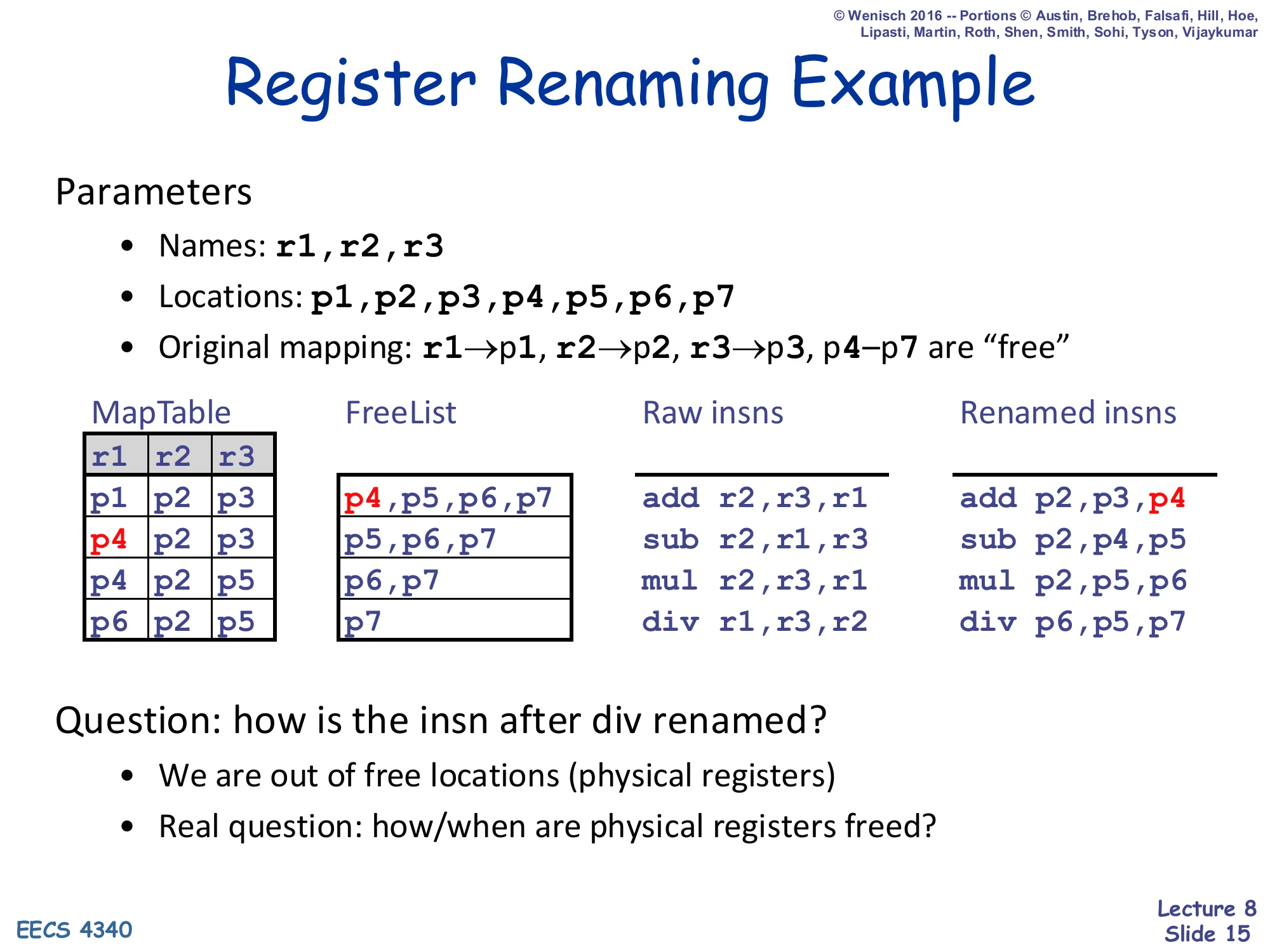
Parameters
- Names:
r1, r2, r3 - Locations:
p1, p2, p3, p4, p5, p6, p7 - Original mapping:
r1 → p1,r2 → p2,r3 → p3,p4–p7are “free”
| MapTable r1 r2 r3 | FreeList | Raw insns | Renamed insns |
|---|---|---|---|
| p1 p2 p3 | p4,p5,p6,p7 | add r2,r3,r1 | add p2,p3,p4 |
| p4 p2 p3 | p5,p6,p7 | sub r2,r1,r3 | sub p2,p4,p5 |
| p4 p2 p5 | p6,p7 | mul r2,r3,r1 | mul p2,p5,p6 |
| p6 p2 p5 | p7 | div r1,r3,r2 | div p6,p5,p7 |
Question: how is the insn after div renamed?
- We are out of free locations (physical registers)
- Real question: how/when are physical registers freed?
This worked example shows the renaming algorithm one instruction at a time. Three architectural registers (r1, r2, r3) are renamed onto seven physical locations (p1–p7) with the initial mapping r1→p1, r2→p2, r3→p3 and p4–p7 initially on the free list. For each instruction, the renamer reads the current mapping for each source operand (so add r2,r3,r1 reads r2→p2 and r3→p3 for its sources), pops the destination register’s new physical name from the free list (p4), and updates the map-table entry for the destination. After add: r1→p4. After sub r2,r1,r3 the source r1 reads the new p4 mapping — this is exactly how RAW dependences become physical-register reads, and how false WAW/WAR dependences disappear because each write picks an unused physical register. By the time div is renamed, the free list is empty (p7 was the last entry), so the next instruction can’t rename. That is the “how/when do we free physical registers?” question that slides 16 and 17 answer: we free them when the next overwrite of the same architectural register retires, because at that point no future instruction will ever read the old physical register’s value.
Freeing Registers in P6 and R10K
Show slide text
Freeing Registers in P6 and R10K
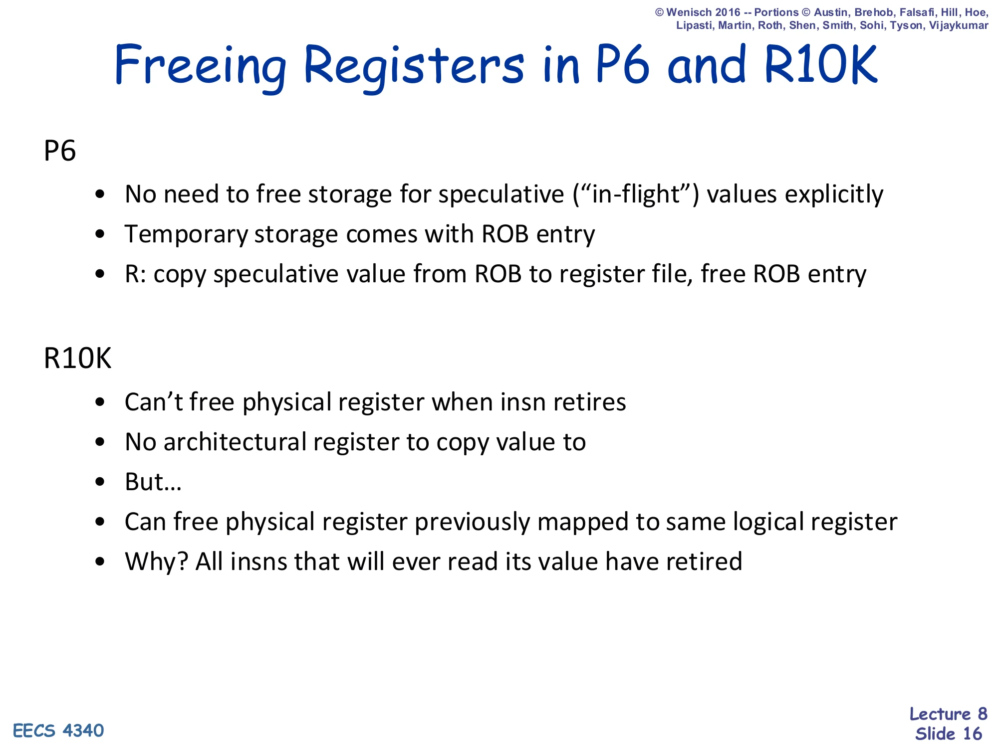
P6
- No need to free storage for speculative (“in-flight”) values explicitly
- Temporary storage comes with ROB entry
- R: copy speculative value from ROB to register file, free ROB entry
R10K
- Can’t free physical register when insn retires
- No architectural register to copy value to
- But…
- Can free physical register previously mapped to same logical register
- Why? All insns that will ever read its value have retired
Freeing storage is dramatically different in the two designs. In P6, every speculative value lives inside the ROB entry that produced it; freeing is automatic — when an instruction retires, the ROB copies its V field into the architectural register file and the entry is recycled. There is no separate “physical register” to track. R10K cannot use this trick because there is no architectural register file to copy to: every value already lives in some physical register and stays there. So the question becomes: when can a physical register be reclaimed? The answer is the slide’s clever insight — when the next writer of the same architectural register retires. At that point every instruction in program order before it has already retired (so all consumers of the old mapping have read their source values), and every instruction after it will rename its sources to the new mapping (so no one will ever read the old physical register again). This is why the R10K ROB entry must store Told (slide 18): retire needs to know which old physical register to push back onto the free list.
Freeing Registers in R10K
Show slide text
Freeing Registers in R10K
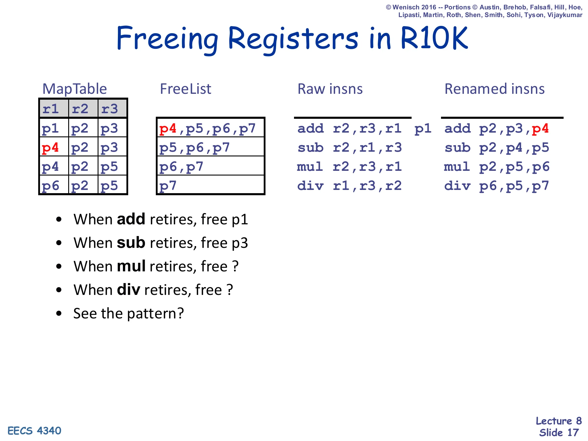
| MapTable r1 r2 r3 | FreeList | Raw insns | Renamed insns |
|---|---|---|---|
| p1 p2 p3 | p4,p5,p6,p7 | add r2,r3,r1 p1 | add p2,p3,p4 |
| p4 p2 p3 | p5,p6,p7 | sub r2,r1,r3 | sub p2,p4,p5 |
| p4 p2 p5 | p6,p7 | mul r2,r3,r1 | mul p2,p5,p6 |
| p6 p2 p5 | p7 | div r1,r3,r2 | div p6,p5,p7 |
- When add retires, free p1
- When sub retires, free p3
- When mul retires, free ?
- When div retires, free ?
- See the pattern?
This slide makes the freeing rule concrete on the same trace. When add retires it overwrites architectural r1 (whose previous mapping was p1); since every instruction in program order before add has already retired and every instruction after add renames its r1 sources to p4, nothing will ever read p1 again — so add’s retire pushes p1 to the free list. Same logic for sub, which targets r3 and bumps p3 off the live set. The two question marks are the exam-style prompt: when mul retires it overwrites r1 again, this time evicting p4 (the value add produced), so mul retire frees p4. When div retires it overwrites r1 once more, evicting p6, so div retire frees p6. The pattern is: at retire, free the previous physical mapping for the destination architectural register — and that previous mapping is exactly the Told field that the ROB entry has been carrying around since dispatch (introduced on slide 18). This is the discipline that lets the renamer reclaim physical storage without ever copying values.
R10K Data Structures
Show slide text
R10K Data Structures
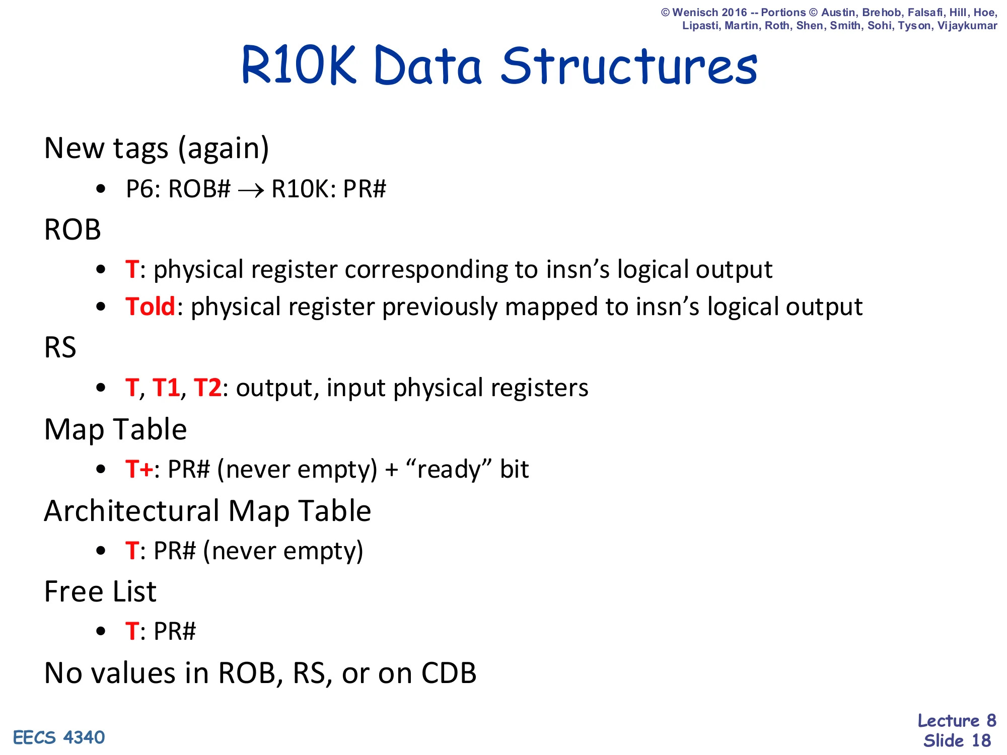
New tags (again)
- P6: ROB# → R10K: PR#
ROB
- T: physical register corresponding to insn’s logical output
- Told: physical register previously mapped to insn’s logical output
RS
- T, T1, T2: output, input physical registers
Map Table
- T+: PR# (never empty) + “ready” bit
Architectural Map Table
- T: PR# (never empty)
Free List
- T: PR#
No values in ROB, RS, or on CDB
This slide is the R10K cheat-sheet. The most important change is in the tag space: in Tomasulo tags were RS numbers, in P6 they were ROB numbers, and in R10K they are physical register numbers (PR#). That single change is what allows values to skip the ROB entirely — an FU writing the physical register file directly is enough, because every consumer is waiting on the same PR# tag. The ROB entry now holds two tags, not values: T (the new physical register this instruction was assigned at dispatch) and Told (the physical register that used to hold the architectural destination, needed for both freeing and rollback). The map table’s T+ field still bundles a tag and a ready bit, but the tag is a PR# and is never empty (since there’s no architectural register file to fall back to). The Architectural Map Table is the new committed-state shadow: it tracks the mapping that would be visible to a precise-state observer, updated only at retire — and is the structure used during serial rollback (slides 30–34). The slide’s last line is the punchline: “No values in ROB, RS, or on CDB” — values live exclusively in the physical register file.
R10K Data Structures (initial state)

Show slide text
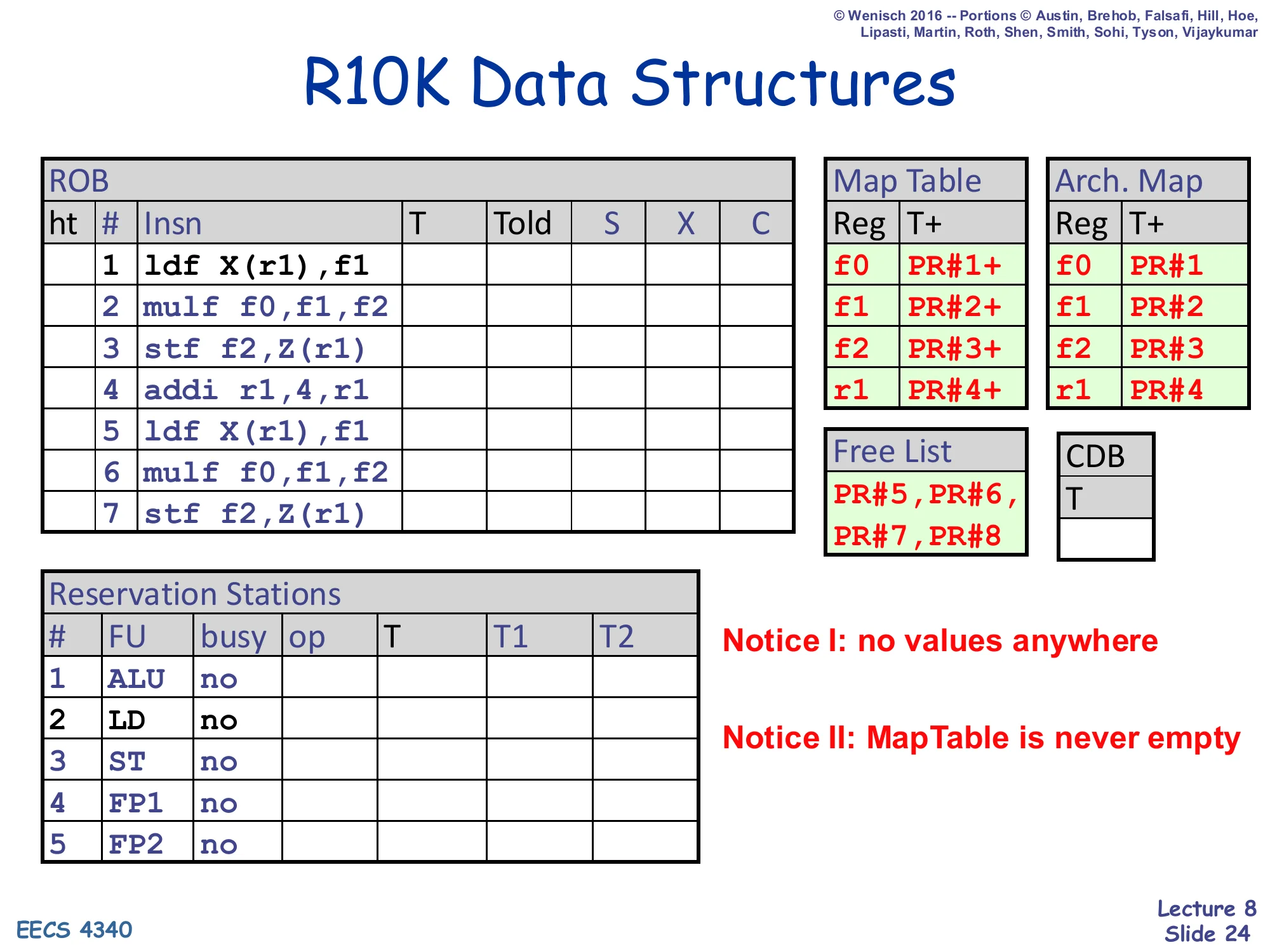
R10K Data Structures
ROB (ht, #, Insn, T, Told, S, X, C):
| # | Insn |
|---|---|
| 1 | ldf X(r1),f1 |
| 2 | mulf f0,f1,f2 |
| 3 | stf f2,Z(r1) |
| 4 | addi r1,4,r1 |
| 5 | ldf X(r1),f1 |
| 6 | mulf f0,f1,f2 |
| 7 | stf f2,Z(r1) |
Map Table and Arch. Map (Reg / T+ and Reg / T+):
| Reg | Map T+ | Arch. T+ |
|---|---|---|
| f0 | PR#1+ | PR#1 |
| f1 | PR#2+ | PR#2 |
| f2 | PR#3+ | PR#3 |
| r1 | PR#4+ | PR#4 |
Free List: PR#5, PR#6, PR#7, PR#8.
CDB: column T (no V).
Reservation Stations (#, FU, busy, op, T, T1, T2):
| # | FU | busy |
|---|---|---|
| 1 | ALU | no |
| 2 | LD | no |
| 3 | ST | no |
| 4 | FP1 | no |
| 5 | FP2 | no |
Notice I: no values anywhere
Notice II: MapTable is never empty
This is the initial-state mirror of the P6 snapshot from slide 8, set up so the upcoming cycle-by-cycle walk-through can be compared directly. The instruction trace is identical (the seven-instruction ldf/mulf/stf/addi loop body), but the surrounding tables are R10K-flavored. The ROB now has T/Told columns instead of R/V, the Map Table holds physical-register tags PR#1+ … PR#4+ (the + is the ready bit) and is paired with an Architectural Map Table holding the committed snapshot (note the absence of the + in the Arch. Map — only one bit per entry there). Four physical registers are pre-allocated to the four architectural registers (f0/f1/f2/r1 → PR#1..4) and four more sit on the free list (PR#5..8). The CDB is now a single tag column — there is nowhere on it for a value to ride. The two red “Notice” callouts make the structural contrast explicit: every storage cell that used to hold a value in P6 has been emptied (because values live only in the physical register file off-screen), and the map table holds a physical register tag in every entry rather than ever being “empty / look in regfile.”
R10K Pipeline
Show slide text
R10K Pipeline
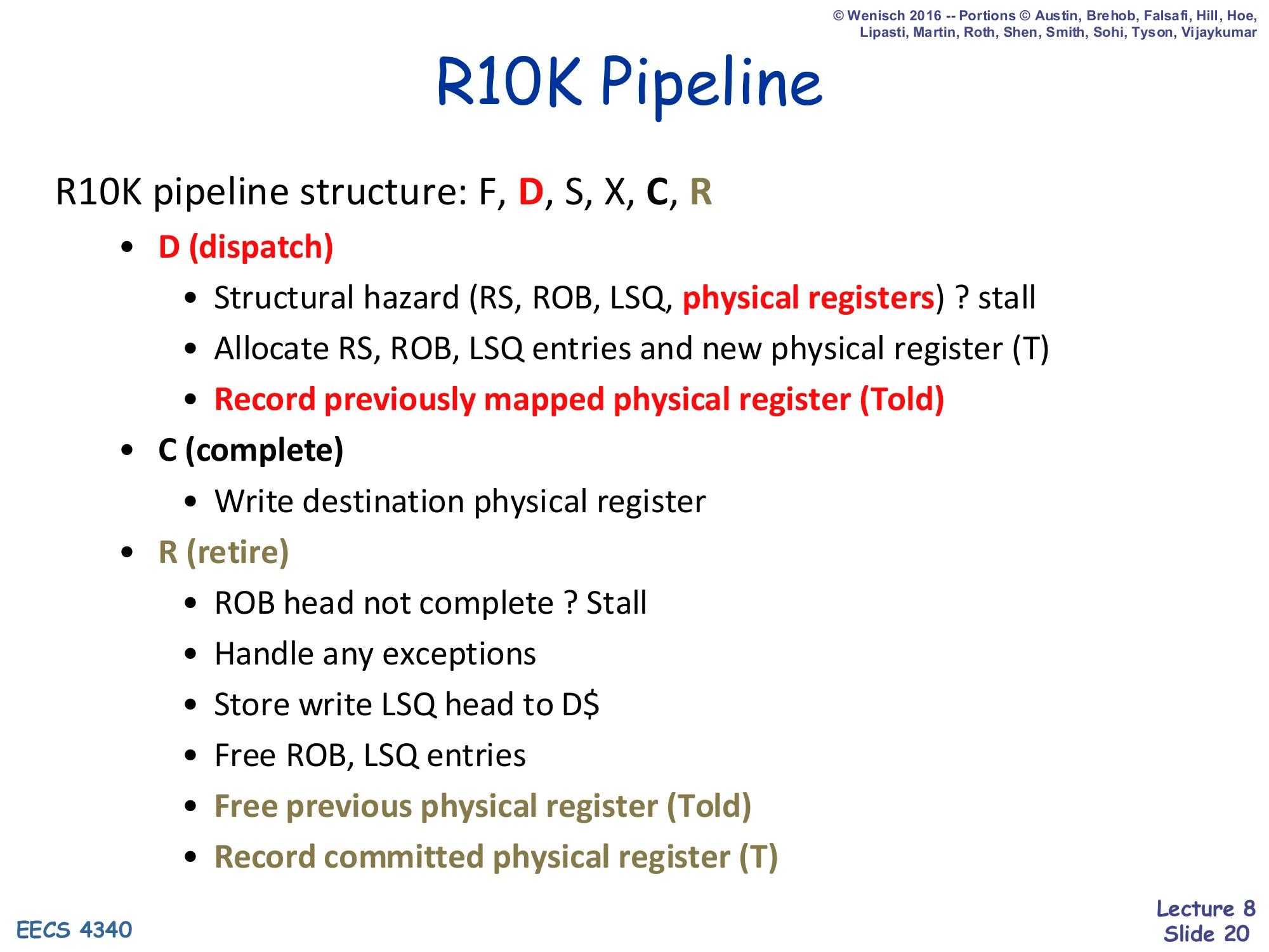
R10K pipeline structure: F, D, S, X, C, R
- D (dispatch)
- Structural hazard (RS, ROB, LSQ, physical registers) ? stall
- Allocate RS, ROB, LSQ entries and new physical register (T)
- Record previously mapped physical register (Told)
- C (complete)
- Write destination physical register
- R (retire)
- ROB head not complete ? Stall
- Handle any exceptions
- Store write LSQ head to D$
- Free ROB, LSQ entries
- Free previous physical register (Told)
- Record committed physical register (T)
This is the R10K pipeline cheat-sheet: F (fetch) → D (dispatch) → S (schedule/issue) → X (execute) → C (complete) → R (retire). Three of the six stages have new responsibilities relative to P6. Dispatch (D) must now check four structural-hazard resources, not three: RS, ROB, LSQ entry, and a free physical register; if any is missing, the front end stalls. When dispatch succeeds it allocates a new physical register T from the free list, writes that mapping into the map table, and crucially records the previous mapping as Told in the ROB entry so retire knows which old physical register to free. Complete (C) is now where the physical register file gets written — no more value-on-CDB hop into a separate ROB value field. Retire (R) has two new R10K-specific actions: free the Told physical register (which is now safe to reclaim because every reader of the old mapping has retired), and record the committed T in the Architectural Map Table for use during precise-state recovery. Notice that no instruction’s result moves between stages — only tags do — which is why the R10K data path is faster.
R10K Dispatch (D)
Show slide text
R10K Dispatch (D)
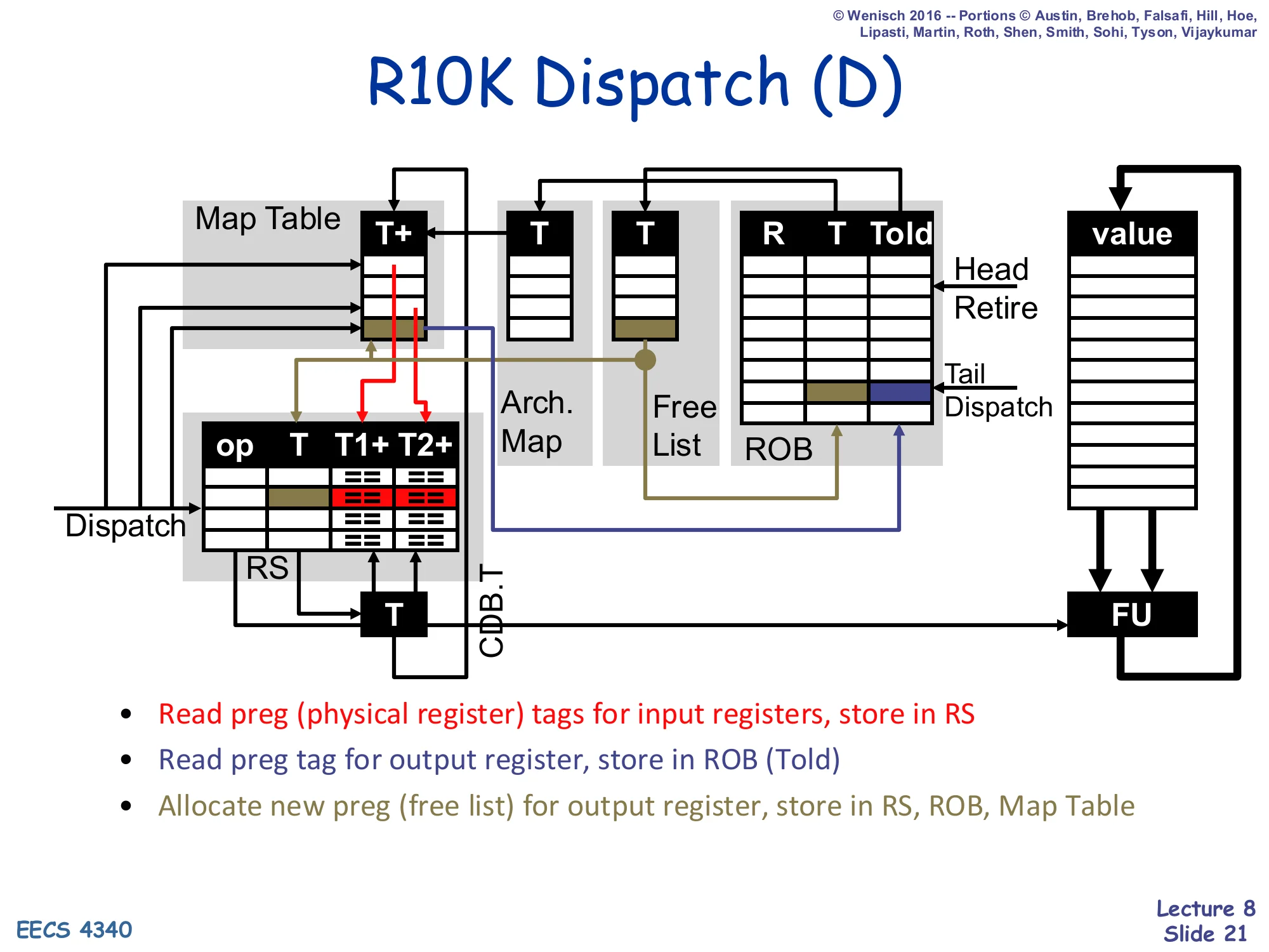
Diagram: at dispatch, the Map Table provides current T+ mappings for source operands (read into RS as T1+/T2+); the Free List provides a new T for the destination, which is written into the RS, the ROB, and the Map Table; the previously mapped physical register from the Map Table is stored into the ROB’s Told field.
- Read preg (physical register) tags for input registers, store in RS
- Read preg tag for output register, store in ROB (Told)
- Allocate new preg (free list) for output register, store in RS, ROB, Map Table
This slide highlights exactly which tag fields move where during R10K dispatch. Three reads happen in parallel from the map table. The two source-operand reads (T1+, T2+) pull the current physical-register tags for each source — these go into the RS so wakeup can later match results from the CDB. The destination-register read pulls the current mapping for the destination (e.g. f1 → PR#2) — and crucially, this old tag is what gets written to the ROB entry’s Told slot, because it is exactly what retire will later need to free. Then the free list hands out a brand-new physical register T (e.g. PR#5), which gets written in three places at once: the RS (so the FU knows where to write its result), the ROB (so retire knows what to record in the Architectural Map), and the Map Table (so subsequent instructions reading this destination as a source will pick up the new mapping). Note that no values move during dispatch — only tags. This is the structural difference from P6 dispatch, where source values were read from the regfile/ROB into the RS’s V1/V2 fields.
R10K Complete (C)
Show slide text
R10K Complete (C)
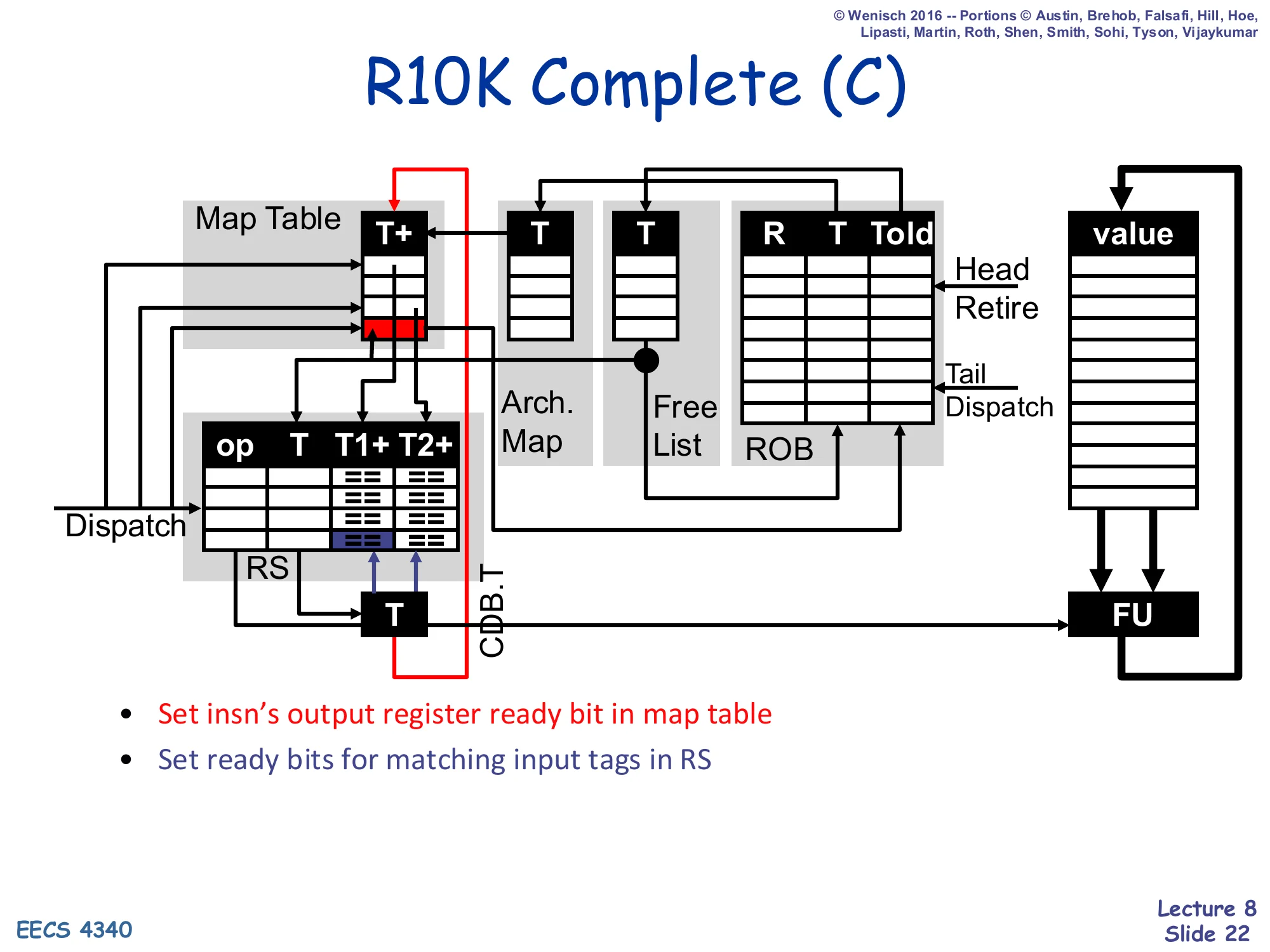
Diagram: when an FU finishes, its tag T is broadcast on CDB.T. The Map Table sets the ready (+) bit on the matching T+ entry. Each RS entry compares CDB.T against its own T1/T2 tags and sets ready bits when they match.
- Set insn’s output register ready bit in map table
- Set ready bits for matching input tags in RS
Complete is the simplest R10K stage. When a functional unit finishes computing a result, two things happen in parallel and that’s it. The result value is written directly into the physical register file at index T (the destination physical register that dispatch allocated). Simultaneously, the tag T is broadcast on CDB.T — the value never appears on the CDB, only the tag. Two consumers snoop that broadcast: (1) the map-table entry whose T+ field matches turns its ready bit on, so any future instruction that dispatches and reads this as a source will know it can read the regfile directly; (2) every RS entry whose T1 or T2 field matches turns the corresponding ready bit on, so currently-waiting instructions can wake up and become eligible for issue. Nothing else moves. Compare to P6 complete, which also had to write the value into the ROB’s V field and broadcast it on CDB.V so that RS entries could capture the value. R10K’s renaming design hoists value storage out of the ROB and the RS, leaving Complete with only tag-bookkeeping work.
R10K Retire (R)
Show slide text
R10K Retire (R)
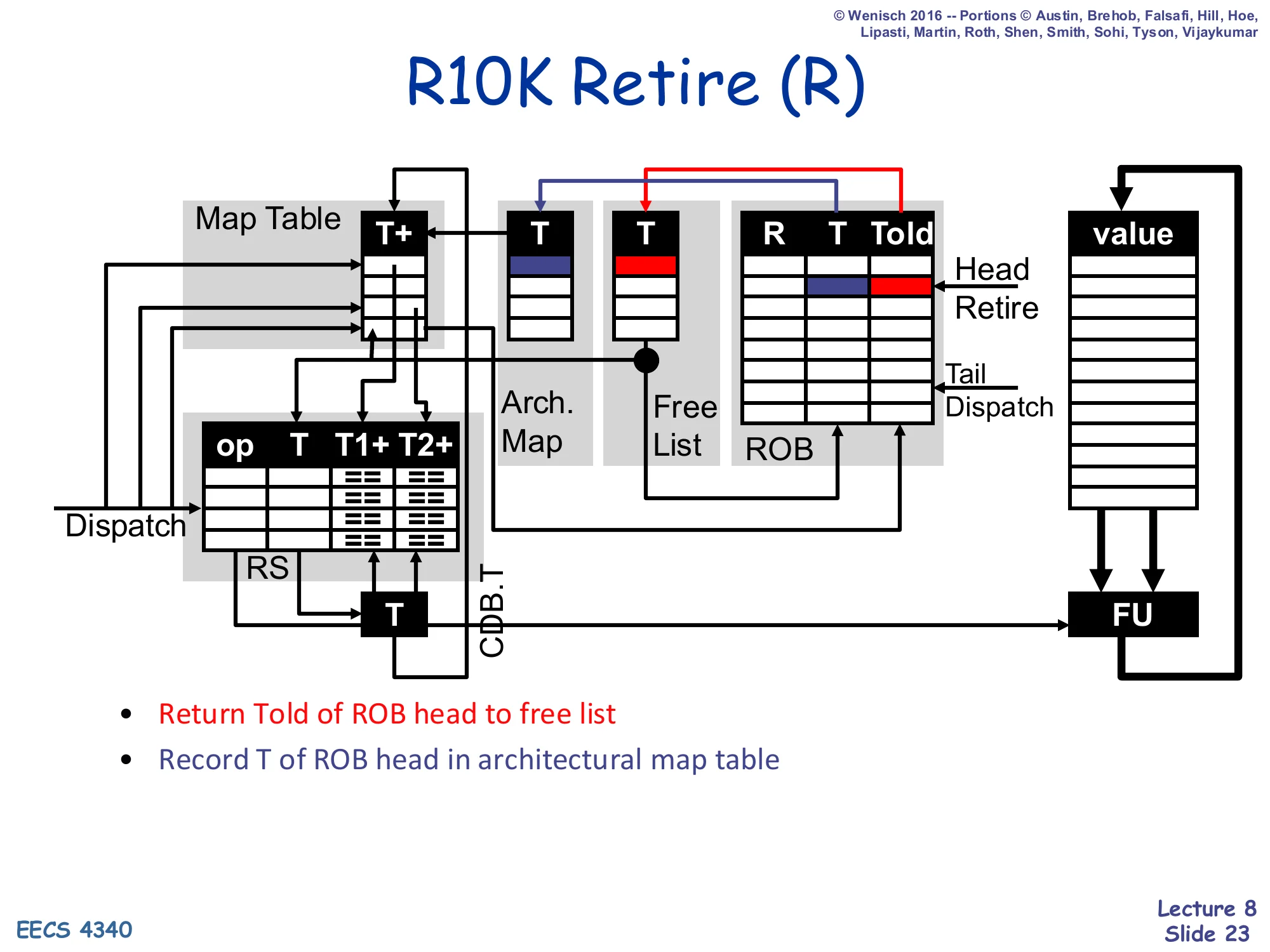
Diagram: the ROB head’s Told is pushed onto the Free List; the ROB head’s T is recorded in the Architectural Map Table at the entry indexed by the architectural destination register R.
- Return Told of ROB head to free list
- Record T of ROB head in architectural map table
Retire in R10K does two specific bookkeeping operations on top of the usual ROB-head pop, exception-handling, and store-buffer drain from the previous slide. First, it pushes the ROB head’s Told field back onto the free list — this is exactly the reclamation rule from slides 16–17, made operational. The retire stage is the only place where the system can be sure that every consumer of the old physical register has already read it (because every earlier instruction has already retired and every later one renames to the new mapping). Second, it copies the ROB head’s T field into the Architectural Map Table at the slot corresponding to the architectural destination register R. The Architectural Map Table is the persistent committed-state mirror of the renaming map — it answers the question “which physical register holds the committed value of architectural register r?” and is precisely the structure that the upcoming serial-rollback recovery (slides 30–34) reads to restore precise state. Notice that retire doesn’t touch the physical register file’s value — committed and speculative values share the same storage, and committing is just a metadata flip.
R10K Data Structures (walk-through start)
Show slide text
R10K Data Structures
Same initial state as slide 19: 7-instruction trace in ROB, Map Table and Arch. Map both pointing f0/f1/f2/r1 → PR#1..PR#4, Free List PR#5,PR#6,PR#7,PR#8, all RS entries idle.
Notice I: no values anywhere
Notice II: MapTable is never empty
This slide is the launch state for the R10K cycle-by-cycle walk-through that runs through slides 25–29 (and continues with the precise-state rollback variant on slides 31–34). It is identical to slide 19 — the instruction trace, the four pre-allocated physical registers, the four free-list entries, and the empty RS — and the two red “Notice” callouts are the same. The reason the slide is repeated is rhetorical: with the dispatch/complete/retire pipeline now defined (slides 20–23), the reader has all the rules needed to step the simulation forward. Each subsequent “R10K: Cycle N” slide will dispatch one or more instructions per cycle, advance any executing FUs, and retire any completed ROB heads, with the highlighted cells showing exactly which fields each pipeline stage touched. Watch how the free list drains as instructions enter D, how the Map Table’s T+ ready bits get flipped at C, and how the Arch. Map updates lag behind the Map Table — exactly mirroring the OoO/iO split that the lecture’s summary slide (37) calls out.
R10K: Cycle 1
Show slide text
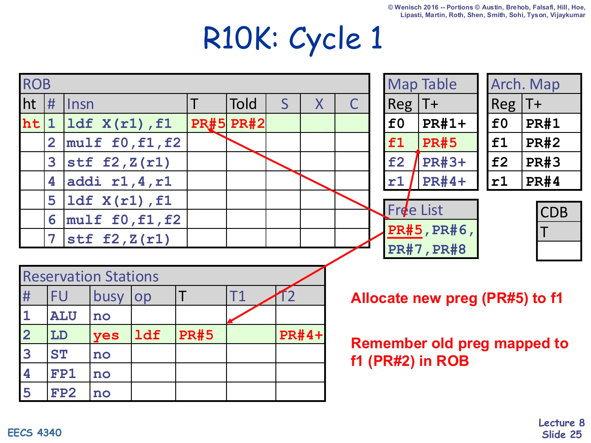
R10K: Cycle 1
ROB#1 ldf X(r1),f1 is dispatched. ROB row 1: T=PR#5, Told=PR#2. Map Table updates f1 → PR#5. Free List shrinks to PR#5,PR#6,PR#7,PR#8 → PR#6,PR#7,PR#8 after pop. RS#2 (LD) becomes busy with op ldf, T=PR#5, T2=PR#4+ (source r1 already ready in regfile).
- Allocate new preg (PR#5) to f1
- Remember old preg mapped to f1 (PR#2) in ROB
Cycle 1 dispatches the first instruction, ldf X(r1),f1. The dispatch stage executes the recipe from slide 21 in one step. Because the destination is f1, the renamer reads the current f1 mapping (PR#2) from the Map Table and writes it as Told=PR#2 in the ROB entry — this is the physical register that retire will eventually free. It pops PR#5 off the free list and writes it as T=PR#5 in the same ROB entry, in the LD reservation station, and in the Map Table at row f1. For sources, r1 is the only operand and its current mapping is PR#4 with the ready bit set (PR#4+), so the RS entry’s T2 field captures PR#4+ — meaning the load is immediately wakeup-eligible. Notice that no value has been read or moved; everything is tag bookkeeping. The two highlighted callouts on the slide name the two key effects: a new physical register (PR#5) is now associated with f1, and the previous mapping (PR#2) is parked in the ROB entry awaiting retire-time freeing.
R10K: Cycle 2
Show slide text
R10K: Cycle 2
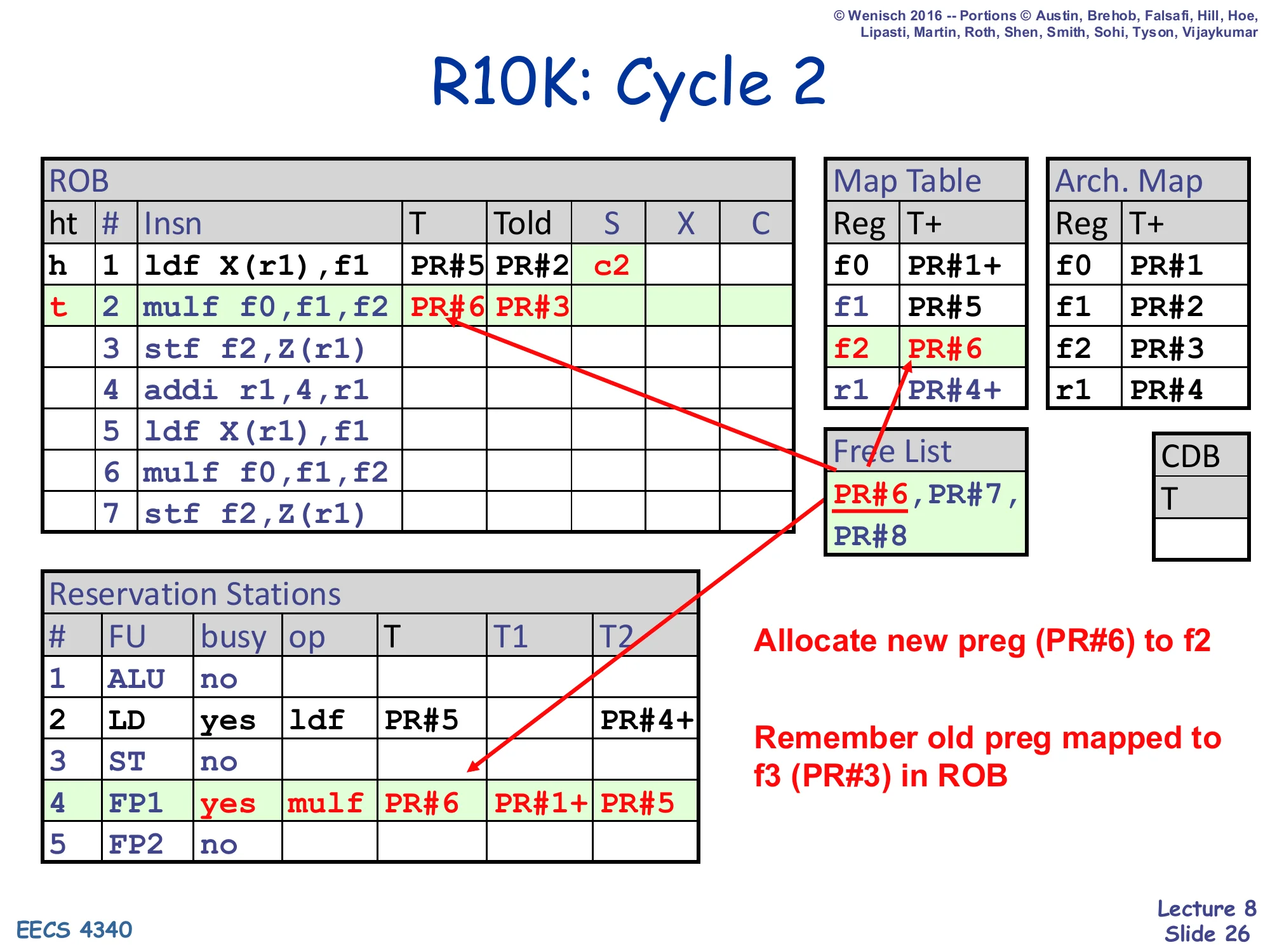
ROB#2 mulf f0,f1,f2 is dispatched. ROB#2: T=PR#6, Told=PR#3. Map Table updates f2 → PR#6. Free List shrinks to PR#6,PR#7,PR#8 → PR#7,PR#8. ROB#1 entered S (started at c2). RS#4 (FP1) busy: op mulf, T=PR#6, T1=PR#1+ (f0 already ready), T2=PR#5 (f1 not ready, waiting on ldf).
- Allocate new preg (PR#6) to f2
- Remember old preg mapped to f3 (PR#3) in ROB
Cycle 2 dispatches mulf f0,f1,f2. Same recipe: pop PR#6 from the free list, record Told=PR#3 (the previous mapping for f2), update the Map Table so f2 → PR#6. The interesting part is source renaming. Because f0’s map-table entry is still PR#1+ (committed and never overwritten in the trace), the multiply reads T1=PR#1+ and is immediately ready on its first source. But f1’s map-table entry is now PR#5 — set just last cycle by the dispatching ldf — and is not yet ready (no +). So the multiply enters the FP1 RS with T2=PR#5 (no ready bit) and will wait there until the load completes and broadcasts PR#5 on the CDB. Meanwhile ROB#1’s S field flips to c2 because the load issued this cycle. Note the subtle correctness property: the multiply will read f1’s correct producer because dispatch picked up the post-rename mapping PR#5, not the pre-rename PR#2 — exactly how RAW dependencies are tracked in R10K.
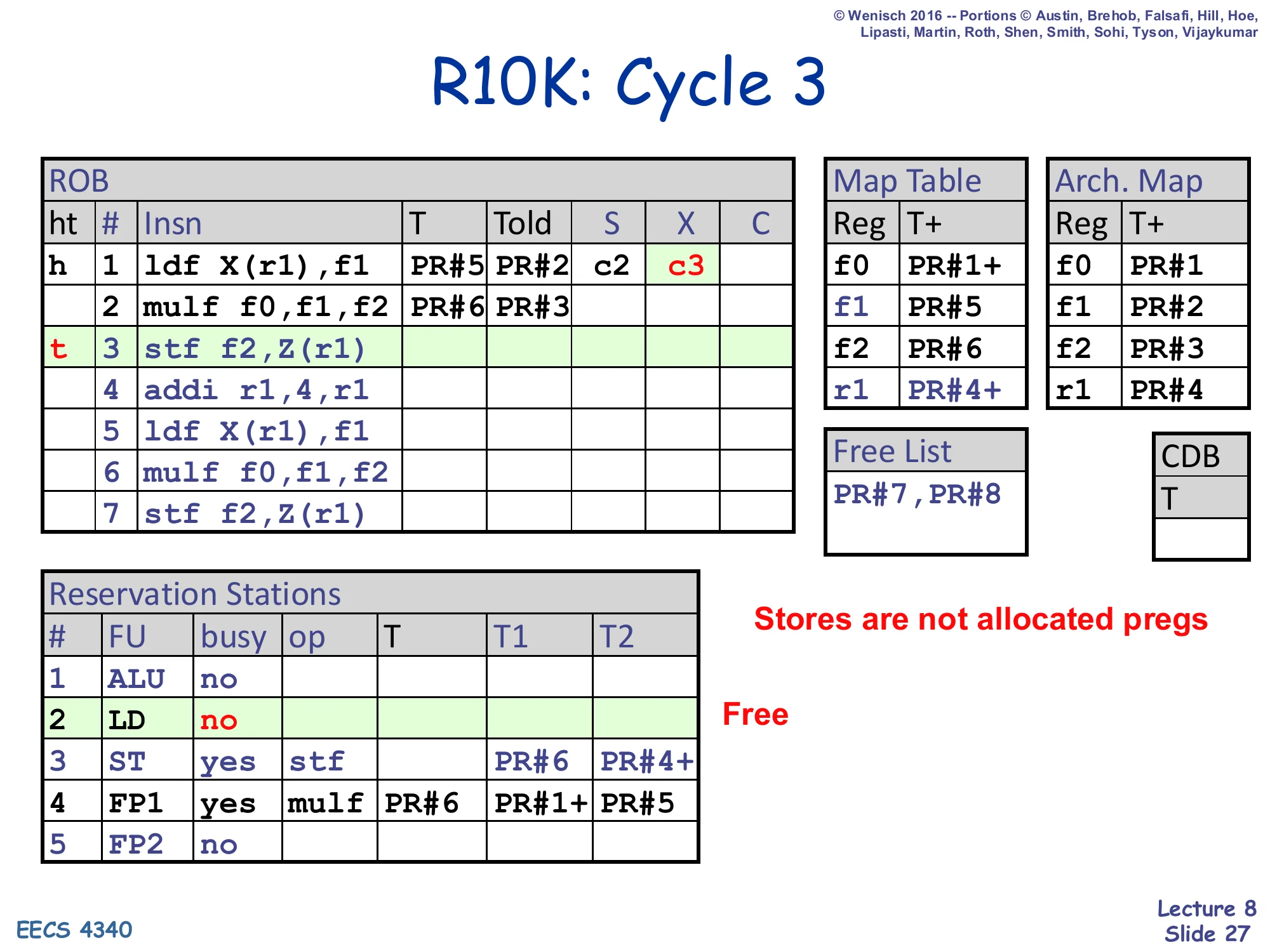
R10K: Cycle 3
Show slide text
R10K: Cycle 3
ROB#3 stf f2,Z(r1) is dispatched. ROB#3 has no T (stores don’t write a logical register). Map Table unchanged. Free List unchanged: PR#7,PR#8. RS#3 (ST) busy: op stf, T1=PR#6 (f2 not ready, waits on mulf), T2=PR#4+ (r1 ready). RS#2 (LD) is freed (op completed). ROB#1 has X=c3.
- Stores are not allocated pregs
- Free (RS#2 LD)
Cycle 3 dispatches the store stf f2,Z(r1). Stores are special in R10K because they don’t write any architectural register — the destination of stf is a memory address, not a register name. The slide makes this point with the highlighted line “Stores are not allocated pregs”: the store gets a ROB entry and an RS entry but never pops a physical register from the free list, and its ROB entry has no T or Told to track. The store’s two source tags are f2 (currently mapped to PR#6, not yet ready — it’s waiting on the multiply) and r1 (currently PR#4+, ready). Two other things happen this cycle. First, the load ldf finishes its execute stage and frees its RS entry — that’s the “Free” callout next to RS#2 — but its ROB entry stays alive until retire. Second, the load’s X field is recorded in the ROB as c3. Note that stores still go through the LSQ for memory ordering, which is why the next lecture (L09) is dedicated to memory scheduling.
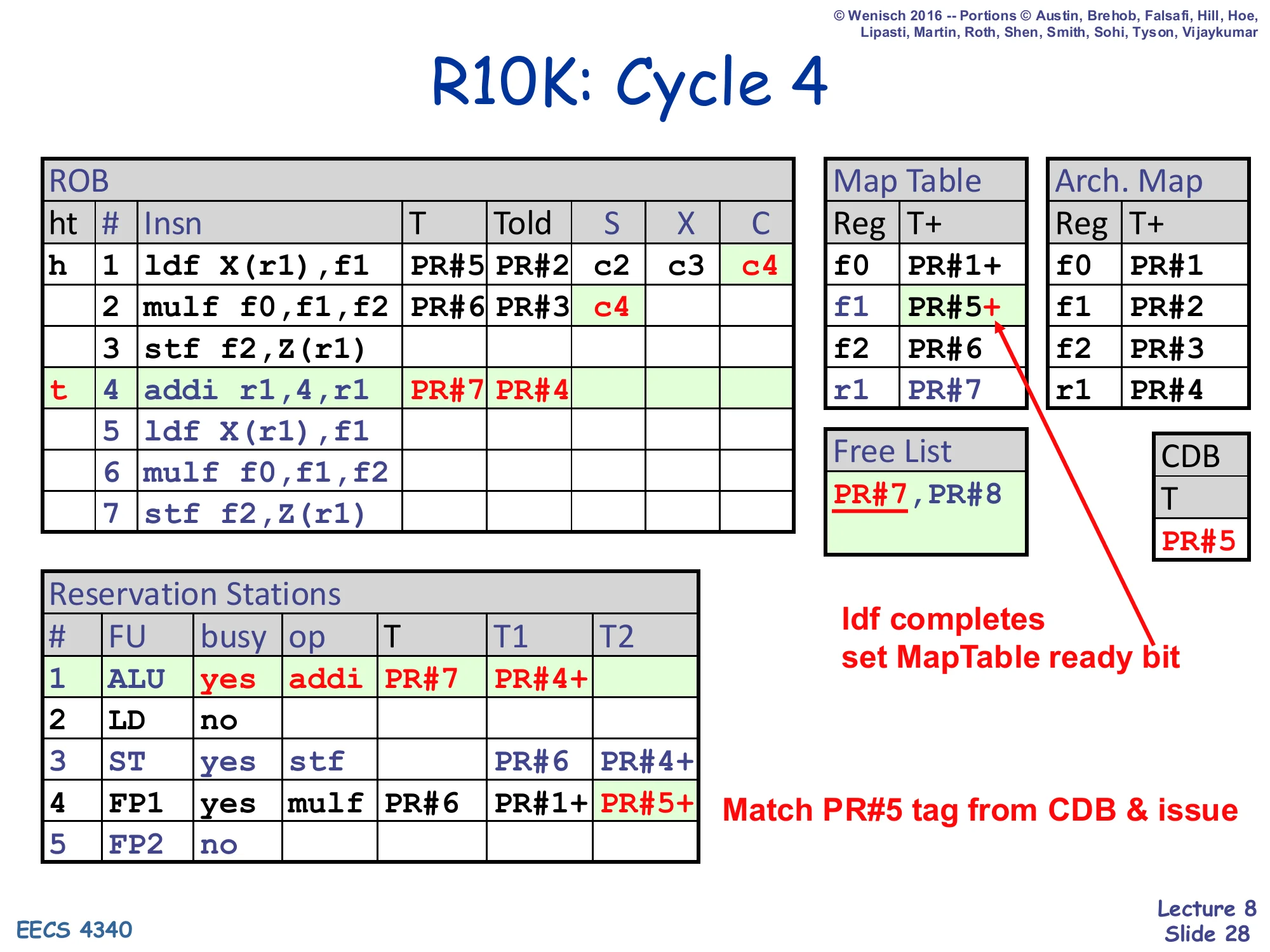
R10K: Cycle 4
Show slide text
R10K: Cycle 4
ROB#4 addi r1,4,r1 is dispatched. ROB#4: T=PR#7, Told=PR#4. Map Table updates r1 → PR#7. Free List shrinks to PR#8. RS#1 (ALU) busy: op addi, T=PR#7, T1=PR#4+ (r1 ready). ROB#1 finishes — C=c4 recorded. CDB broadcasts T=PR#5, which sets the + ready bit on Map Table row f1 (now PR#5+) and wakes up RS#4 FP1 entry’s T2 from PR#5 to PR#5+.
- ldf completes, set MapTable ready bit
- Match PR#5 tag from CDB & issue
Cycle 4 has the most action so far. On the dispatch side, addi r1,4,r1 enters the pipeline: it pops PR#7 from the free list, records Told=PR#4 (the prior r1 mapping) in the ROB, updates the Map Table so r1 → PR#7, and sits in RS#1 with both sources already ready. On the complete side, the original ldf finishes — C=c4 is recorded in ROB#1, the load’s tag PR#5 rides the CDB, and two snoops fire. First, the Map Table row for f1 flips its ready bit so the entry becomes PR#5+ — this means any future instruction that dispatches with f1 as a source will now see a ready operand and can issue right away. Second, RS#4 (the waiting mulf) sees its T2 tag match the CDB, flips that ready bit, and is now wakeup-eligible. The slide foreshadows that the multiply will issue from RS#4 as soon as a free FP unit is available. All of this happens with no values on the CDB — only the tag PR#5.
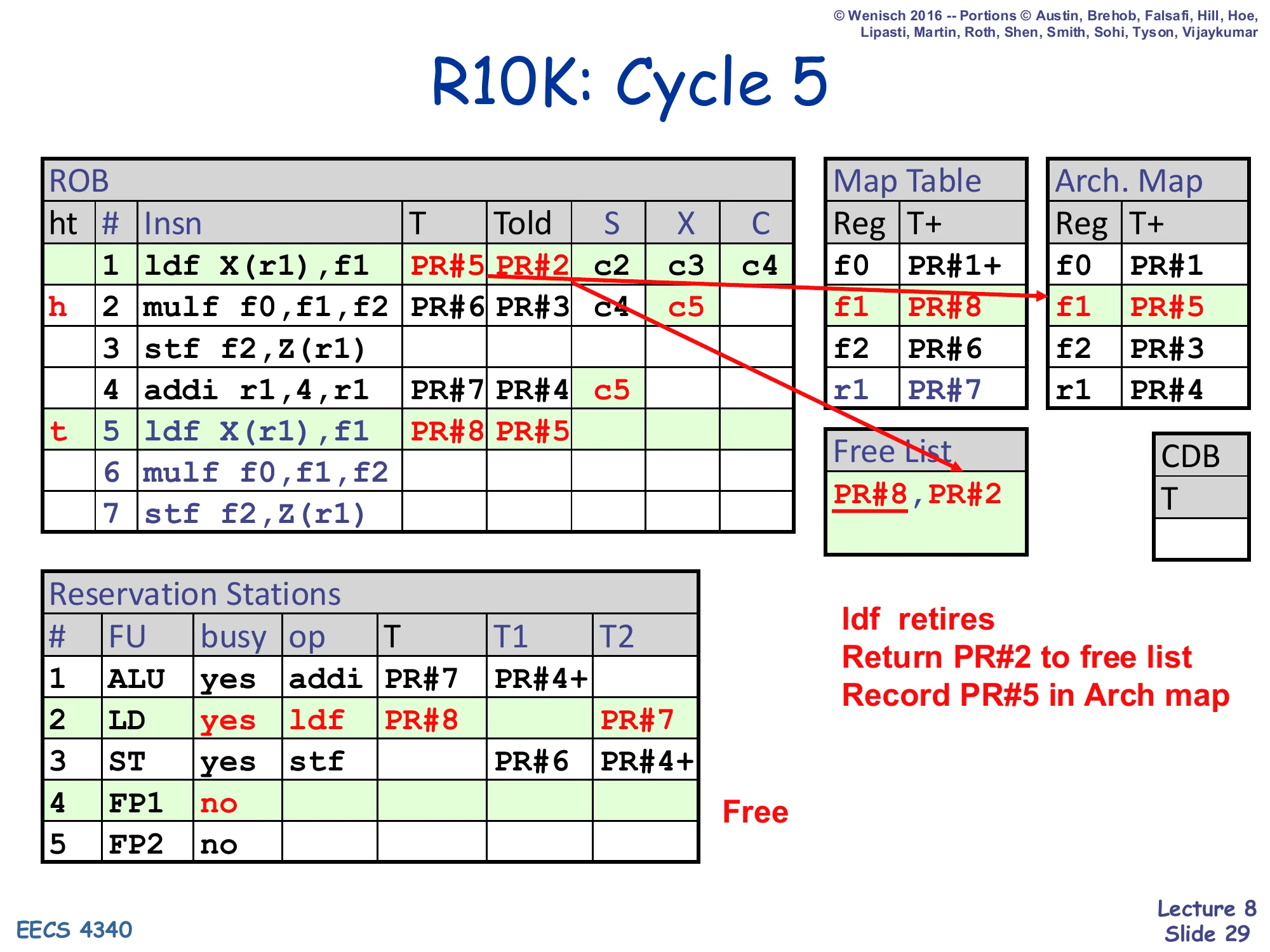
R10K: Cycle 5
Show slide text
R10K: Cycle 5
ROB#5 ldf X(r1),f1 is dispatched. ROB#5: T=PR#8, Told=PR#5. Map Table updates f1 → PR#8. Free List shrinks to PR#8 → empty (after pop). After ROB#1 retires this cycle: Told=PR#2 is returned to free list (Free List becomes PR#2). Arch. Map updates f1 → PR#5. RS#2 (LD) busy with the new ldf (T=PR#8, T2=PR#7 waiting on addi). ROB head pointer h moves from row 1 to row 2.
- ldf retires
- Return PR#2 to free list
- Record PR#5 in Arch map
Cycle 5 brings the first retire. ROB#1’s load is at the head and C is set, so retire fires: it pushes ROB#1’s Told (PR#2) onto the free list and copies ROB#1’s T (PR#5) into the Architectural Map Table at row f1. After the retire, f1’s committed mapping has caught up with its speculative mapping. Simultaneously, the second ldf is dispatched into ROB#5, popping PR#8 and recording Told=PR#5 (which itself was just allocated four cycles ago — this is exactly the freeing pattern from slide 17). The new ldf reads source r1 from the Map Table and gets T2=PR#7 (waiting on the in-flight addi) — note this is the second iteration of the loop body, demonstrating that R10K can have two ldf X(r1) loads in flight whose f1 destinations are renamed to two different physical registers (PR#5 and PR#8), so the WAW hazard between iterations is structurally impossible. Watch the free list: it transiently becomes empty when PR#8 is popped, but is replenished one cycle later by the retire of ROB#1.
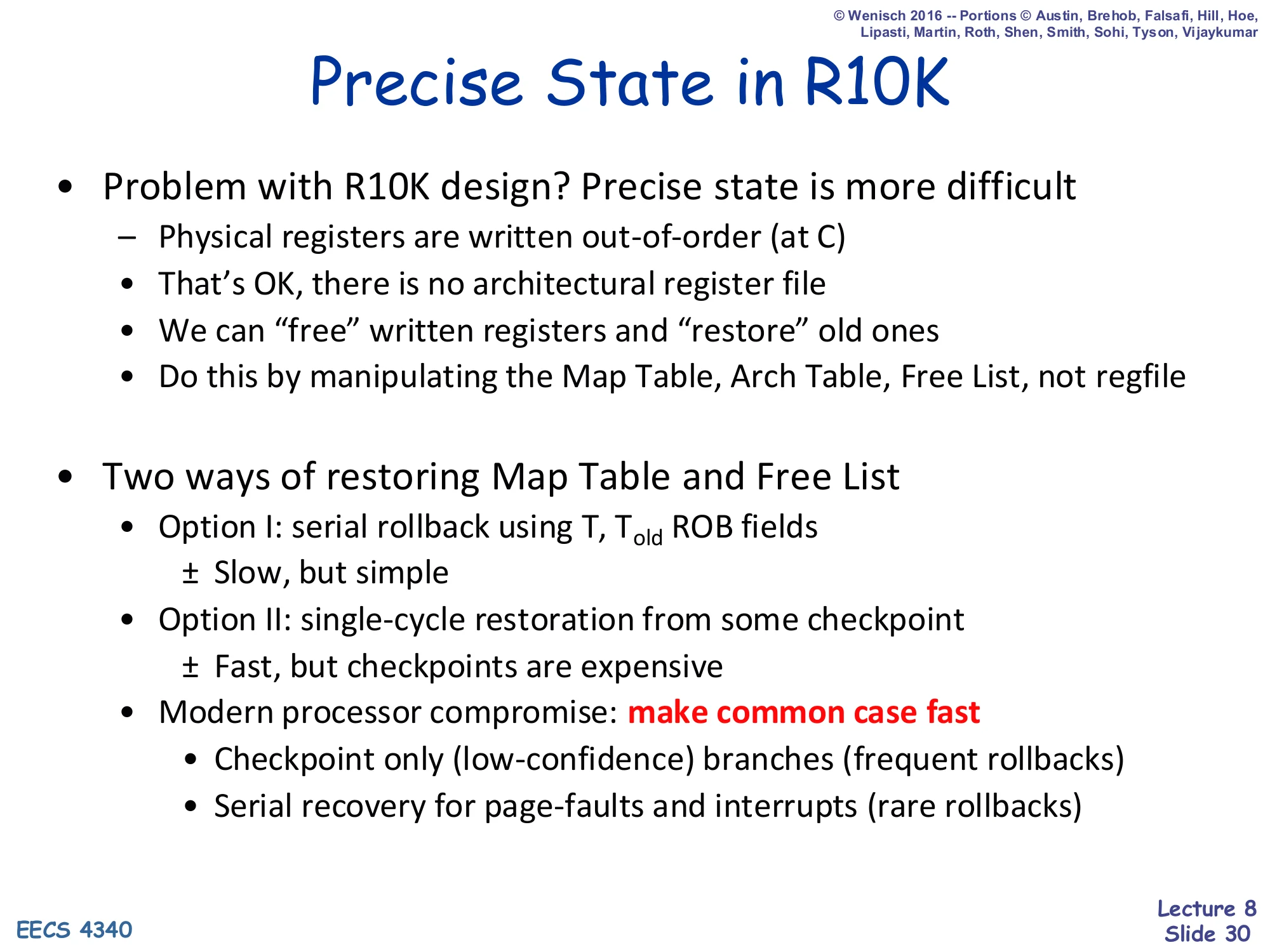
Precise State in R10K
Show slide text
Precise State in R10K
- Problem with R10K design? Precise state is more difficult
- Physical registers are written out-of-order (at C)
- That’s OK, there is no architectural register file
- We can “free” written registers and “restore” old ones
- Do this by manipulating the Map Table, Arch Table, Free List, not regfile
- Two ways of restoring Map Table and Free List
- Option I: serial rollback using T, Told ROB fields
- ± Slow, but simple
- Option II: single-cycle restoration from some checkpoint
- ± Fast, but checkpoints are expensive
- Modern processor compromise: make common case fast
- Checkpoint only (low-confidence) branches (frequent rollbacks)
- Serial recovery for page-faults and interrupts (rare rollbacks)
- Option I: serial rollback using T, Told ROB fields
This is the precise-state cost slide for R10K — the flip side of slide 9’s “P6 has free precise state.” The problem: physical registers are written out of program order at Complete, so the regfile contents are an in-progress mix of speculative and committed values. There’s no architectural register file to fall back on like P6 had. The fix is to restore precise state by manipulating only the metadata (Map Table, Architectural Map Table, Free List) — the physical register file’s values are left alone, because each architectural register’s committed value still lives in whatever physical register the Architectural Map Table points to. Two recovery strategies exist with opposite tradeoffs. Option I (serial rollback): walk the ROB backwards from tail to flush point, freeing each entry’s T and restoring Told into the Map Table. Simple but takes one cycle per ROB entry. Option II (checkpointing): snapshot the entire Map Table at chosen points so recovery is one cycle, but each checkpoint is a full copy of the table. Real machines compromise: checkpoint at low-confidence branches (where misprediction-driven rollbacks are common and must be fast) and serial-recover for the rare cases like page faults and interrupts.
R10K: Cycle 5 (with precise state)
Show slide text
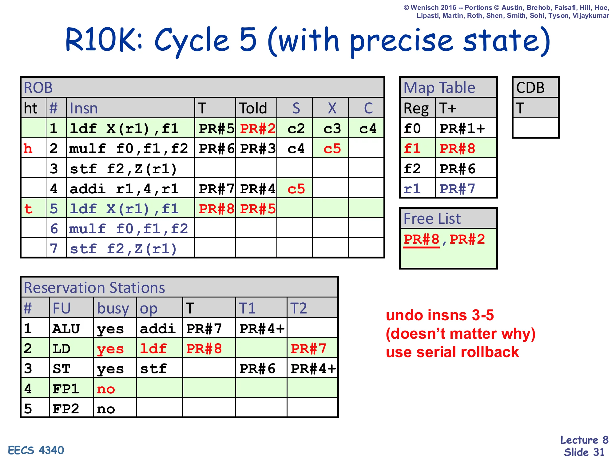
R10K: Cycle 5 (with precise state)
Same state as cycle 5: ROB#1 has retired, ROB#2–5 dispatched. Map Table: f0→PR#1+, f1→PR#8, f2→PR#6, r1→PR#7. Arch. Map: f0→PR#1, f1→PR#5, f2→PR#3, r1→PR#4. Free List: PR#8, PR#2. ROB head h at row 2, tail t at row 5.
undo insns 3-5 (doesn’t matter why) → use serial rollback
This slide kicks off the serial rollback walk-through. The setup matches the end of cycle 5: the first ldf has retired (so its T=PR#5 is now in the Architectural Map Table), and instructions 2–5 are still in flight in the ROB. Suddenly something — the slide says “doesn’t matter why,” but think page fault, branch misprediction, or external interrupt — requires undoing instructions 3, 4, and 5 to restore precise state. The mechanism is Option I from slide 30: serial rollback. The recovery hardware will walk the ROB backwards from the tail, processing one entry per cycle, and at each entry it will undo the dispatch-time effects: reclaim the T physical register, restore Told into the Map Table at the appropriate architectural slot, and free the ROB/RS/LSQ entries. The next three slides (32, 33, 34) show this happening one entry at a time — undoing ROB#5’s renaming first, then ROB#4, then ROB#3, until the tail pointer reaches the kept boundary.
R10K: Cycle 6 (with precise state)
Show slide text
R10K: Cycle 6 (with precise state)
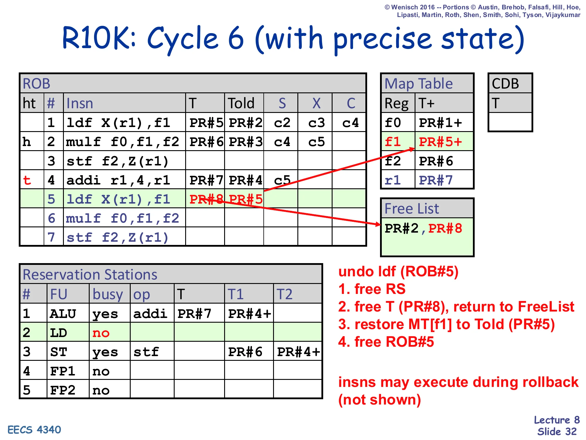
Undo ldf (ROB#5):
- free RS
- free T (PR#8), return to FreeList
- restore MT[f1] to Told (PR#5)
- free ROB#5
insns may execute during rollback (not shown)
Resulting Map Table: f0→PR#1+, f1→PR#5+, f2→PR#6, r1→PR#7. Free List: PR#2, PR#8.
Cycle 6 of the rollback walk-through undoes ROB#5 (the second ldf X(r1),f1). The four-step undo recipe is the inverse of the dispatch recipe. Step 1: free the RS entry that the load was sitting in. Step 2: push the load’s T=PR#8 back onto the free list — this physical register holds whatever the load may have written, but no future instruction will see those bits because the architectural state is being rewound. Step 3: restore the Map Table by writing Told=PR#5 back into row f1 — this undoes the dispatch-time map-table update so the next instruction that reads f1 will see the previous in-flight producer (which happens to be the original ldf that already retired, hence PR#5+). Step 4: free the ROB entry by moving the tail pointer back from row 5 to row 4. Note the slide’s parenthetical “insns may execute during rollback (not shown)” — the rollback is purely metadata work and does not block the FUs from finishing in-flight ops. After cycle 6 the system has effectively forgotten that the second ldf was ever dispatched.
R10K: Cycle 7 (with precise state)
Show slide text
R10K: Cycle 7 (with precise state)
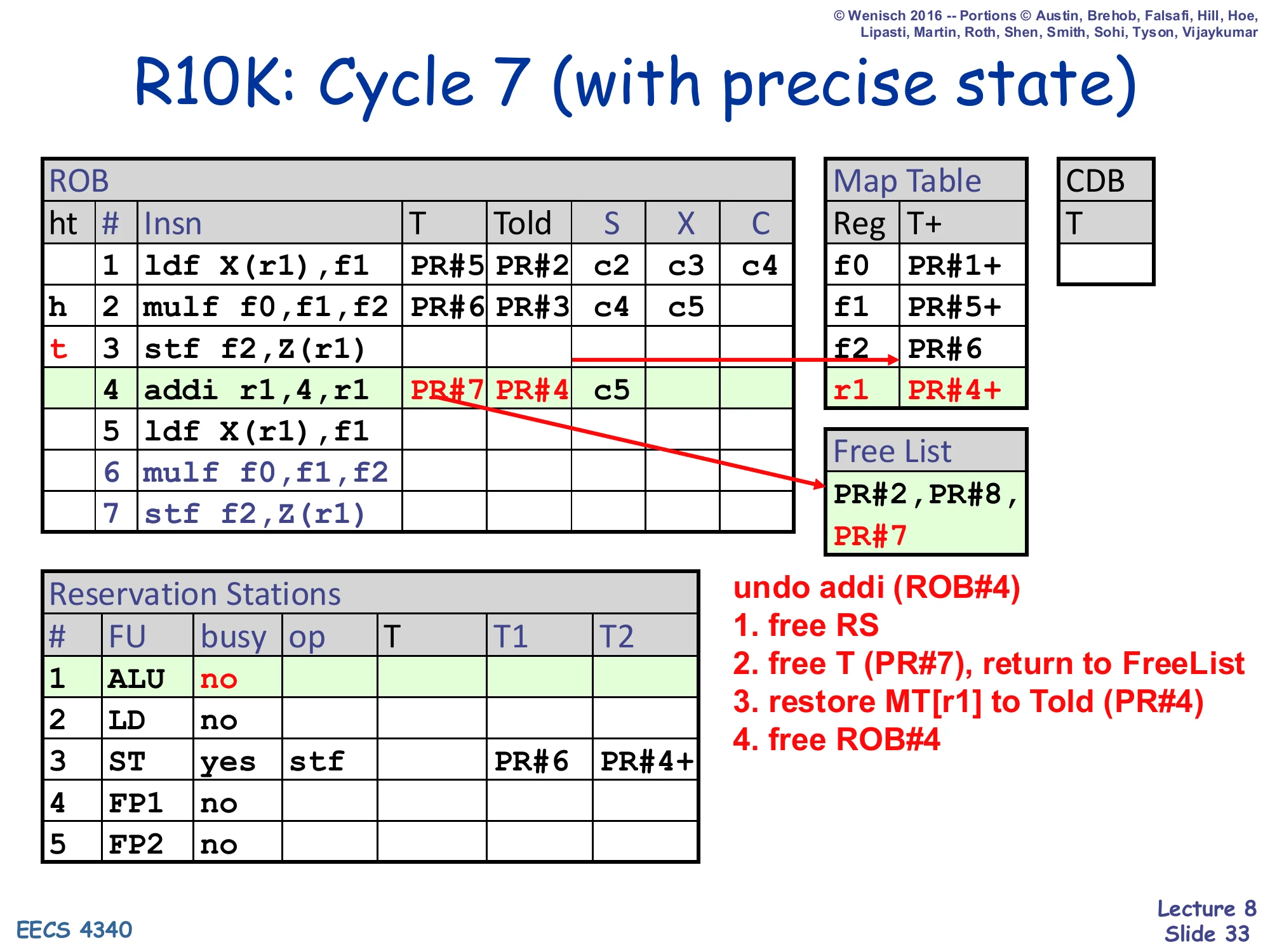
undo addi (ROB#4):
- free RS
- free T (PR#7), return to FreeList
- restore MT[r1] to Told (PR#4)
- free ROB#4
Resulting Map Table: f0→PR#1+, f1→PR#5+, f2→PR#6, r1→PR#4+. Free List: PR#2, PR#8, PR#7.
Cycle 7 of the rollback undoes ROB#4 (addi r1,4,r1). Same four-step recipe as the previous slide. Step 1: free the ALU RS entry. Step 2: return T=PR#7 to the free list. Step 3: restore Told=PR#4 into the Map Table at row r1 — this is the key step that re-establishes the architectural identity of r1. After this write, r1 once again maps to PR#4 (with the ready bit set, since PR#4 was the committed producer before this loop iteration started). Step 4: pop ROB#4 by retreating the tail pointer. The combined effect of cycles 6 and 7 is that the speculative mappings created by ROB#4 and ROB#5 have been completely reversed: r1 → PR#4 and f1 → PR#5 are back, exactly the state that existed at the end of cycle 5 before ROB#4 and ROB#5 were dispatched. One more cycle (slide 34) will undo the store at ROB#3, leaving the ROB in a state where the only in-flight instruction is the still-executing multiply at ROB#2.
R10K: Cycle 8 (with precise state)
Show slide text
R10K: Cycle 8 (with precise state)
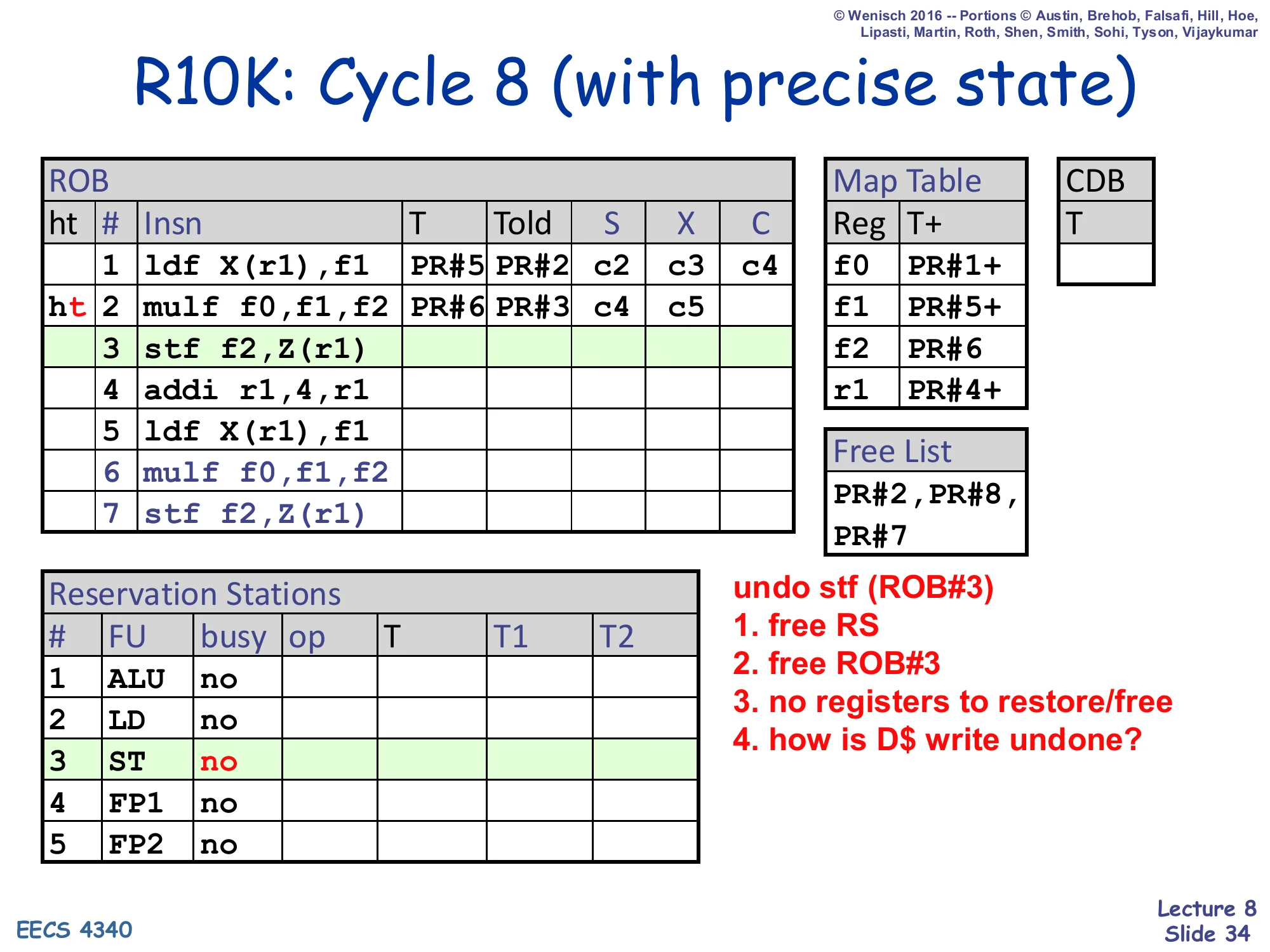
undo stf (ROB#3):
- free RS
- free ROB#3
- no registers to restore/free
- how is D$ write undone?
Resulting Map Table: f0→PR#1+, f1→PR#5+, f2→PR#6, r1→PR#4+. Free List: PR#2, PR#8, PR#7. ROB head ht at row 2 (only mulf remains in-flight).
Cycle 8 finishes the rollback by undoing the store at ROB#3 — and also surfaces one of the few “hard” parts of R10K precise state. Steps 1 and 2 are easy: free the ST RS entry and pop ROB#3 by retreating the tail. Step 3 reminds us that stores don’t allocate physical registers, so there is no T to free or Told to restore — the renaming bookkeeping for stores is empty. But step 4 is the puzzle on the slide: “how is D$ write undone?” Stores update the data cache at retire, so if the store has already retired, the write to memory has already happened and cannot be metadata-rolled-back like register state can. The standard answer (covered fully in L09) is that R10K’s store queue holds stores past retire until they are guaranteed not to be rolled back — and rollback simply has to ensure the bad path’s stores never leave the store queue. After cycle 8 the ROB holds only ROB#1 and ROB#2 (the original ldf plus the still-executing mulf), the Map Table reflects a precise state, and the machine is ready to either re-fetch from the corrected PC or resume executing depending on what triggered the rollback.
P6 vs. R10K (Renaming)
Show slide text
P6 vs. R10K (Renaming)
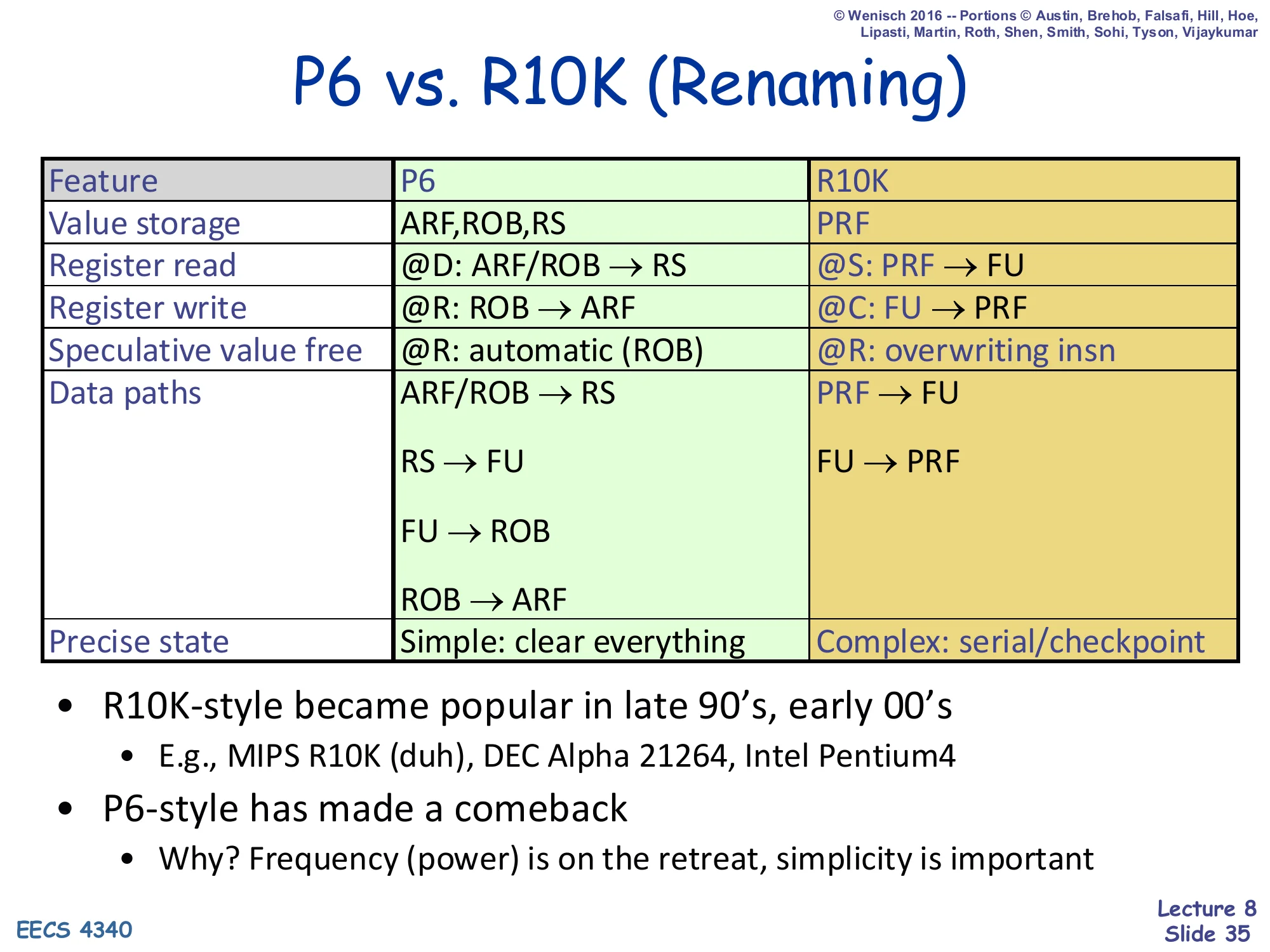
| Feature | P6 | R10K |
|---|---|---|
| Value storage | ARF, ROB, RS | PRF |
| Register read | @D: ARF/ROB → RS | @S: PRF → FU |
| Register write | ROB → ARF | @C: FU → PRF |
| Speculative value free | @R: automatic (ROB) | @R: overwriting insn |
| Data paths | ARF/ROB → RS, RS → FU, FU → ROB, ROB → ARF | PRF → FU, FU → PRF |
| Precise state | Simple: clear everything | Complex: serial/checkpoint |
- R10K-style became popular in late 90’s, early 00’s
- E.g., MIPS R10K (duh), DEC Alpha 21264, Intel Pentium4
- P6-style has made a comeback
- Why? Frequency (power) is on the retreat, simplicity is important
This slide is the L08 synthesis: a six-row matrix that pins down every architectural difference between P6 and R10K. Value storage: P6 spreads values across the architectural register file (ARF), the ROB, and the RS; R10K consolidates them in a single physical register file (PRF). Register read moves from dispatch (P6) to schedule/issue (R10K) — an important shift because R10K reads operands after wakeup, when their physical-register location is already known, while P6 reads them at dispatch and forwards captured values via the CDB. Register write for R10K is just an FU→PRF write; for P6 it’s a value movement first to the ROB and later to the ARF. Speculative-value free is automatic for P6 (the ROB entry’s V slot is reclaimed at retire) but R10K requires the explicit overwriting-insn rule from slide 16. Data paths is the bandwidth story: P6 has four wide value paths (ARF/ROB → RS, RS → FU, FU → ROB, ROB → ARF) versus R10K’s two (PRF → FU, FU → PRF). Precise state is the inverted tradeoff: P6 is simple (flush everything), R10K requires serial or checkpoint recovery. The bottom line: R10K won the late-90s GHz race (R10K, Alpha 21264, Pentium 4); P6-style came back when power-constrained simplicity (e.g. Pentium M) became the priority.
Summary
Show slide text
Summary
-
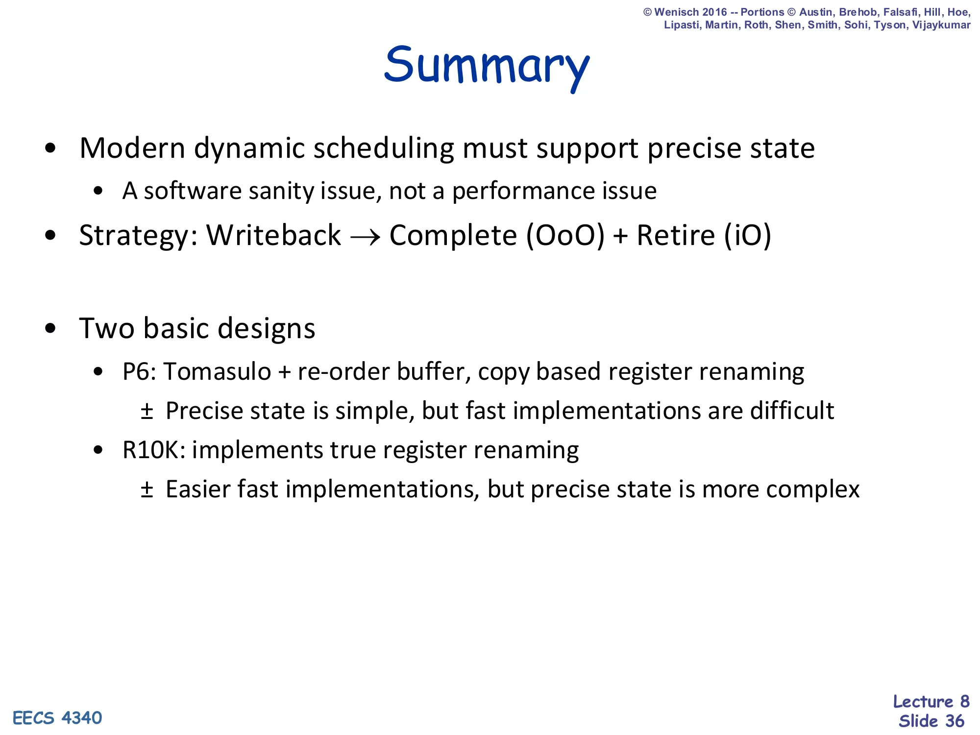
Modern dynamic scheduling must support precise state
- A software sanity issue, not a performance issue
-
Strategy: Writeback → Complete (OoO) + Retire (iO)
-
Two basic designs
- P6: Tomasulo + re-order buffer, copy based register renaming
- ± Precise state is simple, but fast implementations are difficult
- R10K: implements true register renaming
- ± Easier fast implementations, but precise state is more complex
- P6: Tomasulo + re-order buffer, copy based register renaming
The summary slide compresses L08 into three claims. (1) Precise state is mandatory — not because it makes execution faster, but because software (debuggers, exception handlers, OS interrupt code) needs an architecturally observable point at which earlier instructions have all committed and later instructions have none committed. (2) The strategy is to split P5/P4-era “writeback” into two stages: Complete (which can happen out of order, when an FU finishes) and Retire (which happens strictly in program order, at the ROB head). This split is what makes speculation safe. (3) Two implementation styles trade complexity in opposite places. P6 puts speculative values inside the ROB entries — easy precise state (just flush), hard fast clocking (lots of value movement). R10K uses true register renaming with a unified physical register file — easy fast clocking (one value path), hard precise state (serial rollback or checkpointing). Modern designs often combine techniques: most contemporary high-end OoO cores use R10K-style PRF with branch checkpointing, while keeping serial rollback for rare events like page faults — exactly the compromise sketched on slide 30.
Dynamic Scheduling Summary
Show slide text
Dynamic Scheduling Summary
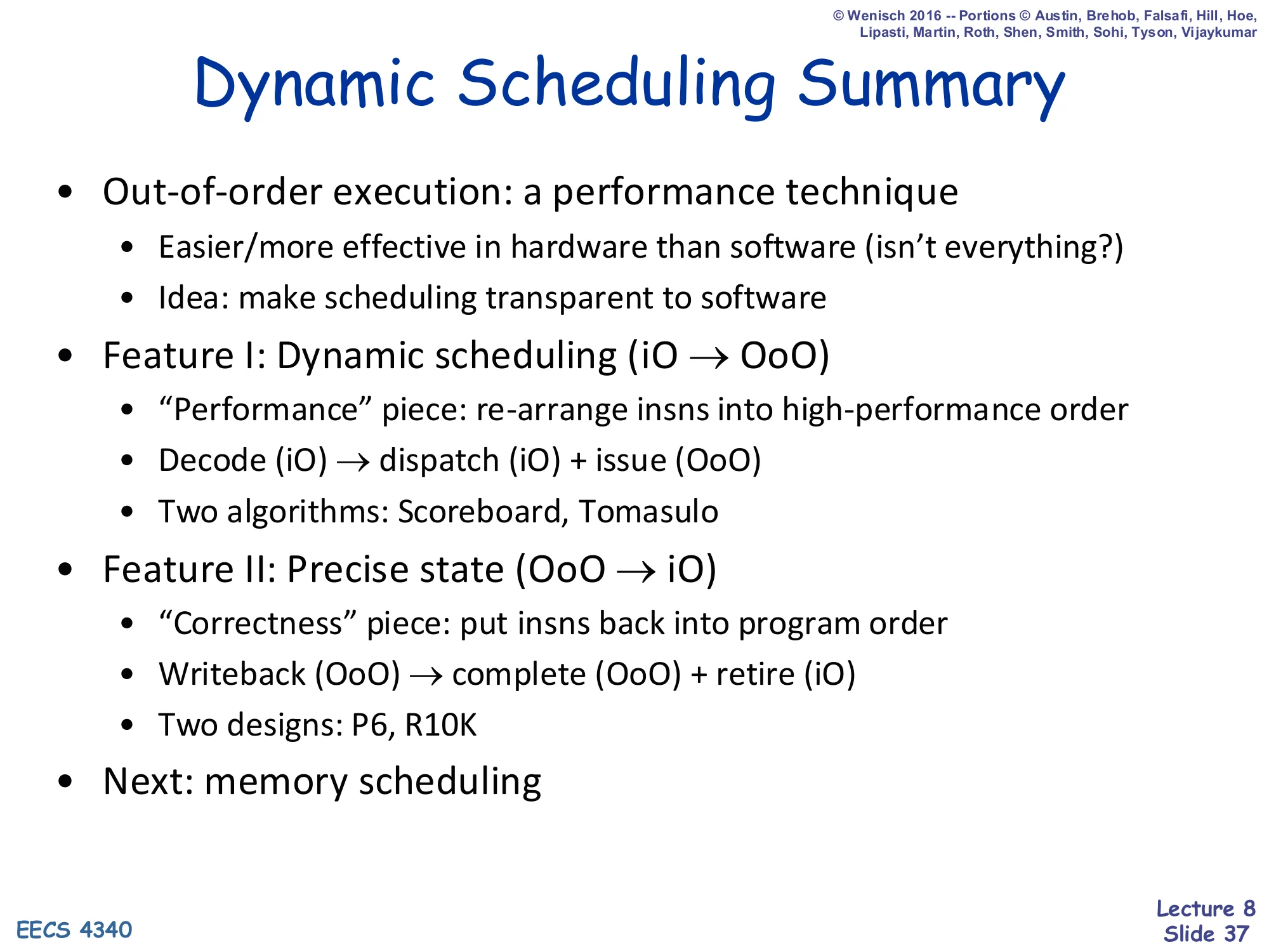
- Out-of-order execution: a performance technique
- Easier/more effective in hardware than software (isn’t everything?)
- Idea: make scheduling transparent to software
- Feature I: Dynamic scheduling (iO → OoO)
- “Performance” piece: re-arrange insns into high-performance order
- Decode (iO) → dispatch (iO) + issue (OoO)
- Two algorithms: Scoreboard, Tomasulo
- Feature II: Precise state (OoO → iO)
- “Correctness” piece: put insns back into program order
- Writeback (OoO) → complete (OoO) + retire (iO)
- Two designs: P6, R10K
- Next: memory scheduling
This slide reframes the entire L05–L08 arc as two orthogonal axes. Feature I: dynamic scheduling is the performance axis (iO → OoO). It splits the old monolithic Decode stage into Decode (still in-order) → Dispatch (still in-order) → Issue (now out of order), so independent instructions can race ahead while a dependent one waits. The two algorithms covered earlier in the term — Scoreboarding (CDC 6600 style, no renaming) and Tomasulo (reservation stations + CDB, with renaming via tags) — are alternative implementations of the same dispatch+issue split. Feature II: precise state is the correctness axis (OoO → iO). It splits the old Writeback stage into Complete (OoO, when the FU finishes) + Retire (iO, at the ROB head). The two designs covered in this lecture — P6 and R10K — are alternative implementations of this split. The two features compose: a real machine picks one Feature I implementation and one Feature II implementation. The next lecture (L09) drops down a level by adding a third axis — memory scheduling — which is where the really hard ordering questions about loads, stores, and the data cache come in.
Readings

Show slide text
Readings
For today:
- The MIPS R10000 Superscalar Microprocessor, https://ieeexplore.ieee.org/abstract/document/491460
Announcements
Show slide text
Announcements
- Project #4
- Due: milestone 1, 13-Mar-26
- Labs
- Monday and Wednesday after spring recess
- Memory and caches, 23-Mar-26
- Module integration, load and store queue, 25-Mar-26