L15 · Virtual Memory
Topic: memory · 32 pages
EECS 4340 Lecture 15 — Virtual Memory
Announcements

Show slide text
Announcements
- Project #4
- Due: May 1, 11:59 PM Eastern Time
- Office hours
- End this week
- Final project presentation
- May 4, 2026
- 8:40 to 9:50 AM
- 8 minutes per group with 2 minutes for questions & answers
- Schedule and example slides on Courseworks
Readings
Show slide text
Readings
For today:
- Appendix L, http://www.cs.yale.edu/homes/abhishek/abhishek-appendix-l.pdf
- Architectural and Operating System Support for Virtual Memory, https://doi.org/10.1007/978-3-031-01757-5
Recap: Prefetching
What is Prefetching?

Show slide text
What is Prefetching?
- Fetch memory ahead of time
- Targets compulsory, capacity, & coherence misses
Big challenges:
- knowing “what” to fetch
- Fetching useless info wastes valuable resources
- “when” to fetch it
- Fetching too early clutters storage
- Fetching too late defeats the purpose of “pre”-fetching
This single-slide recap sets the stage by reminding us that hardware prefetching is a speculative miss-hiding technique whose effectiveness hinges on two orthogonal questions: what address to fetch and when to issue the request. Both can fail. Fetching the wrong block wastes memory bandwidth and can pollute the cache by evicting useful lines (a useless prefetch is worse than no prefetch). Fetching at the wrong time also fails: a prefetch that arrives after the demand reference is too late to hide the miss, while a prefetch that arrives too early can be evicted before its consumer issues. The slide notes that prefetching attacks the three main miss categories from L13 — compulsory (first reference), capacity (working set exceeds cache), and coherence (another core invalidated the line) — but cannot help conflict misses, which are an associativity problem rather than a temporal one. With this recap finished, the lecture pivots from the data side of the cache hierarchy to the address side: how does a process even produce the addresses the cache sees?
Improving Cache Performance: Summary
Show slide text
Improving Cache Performance: Summary
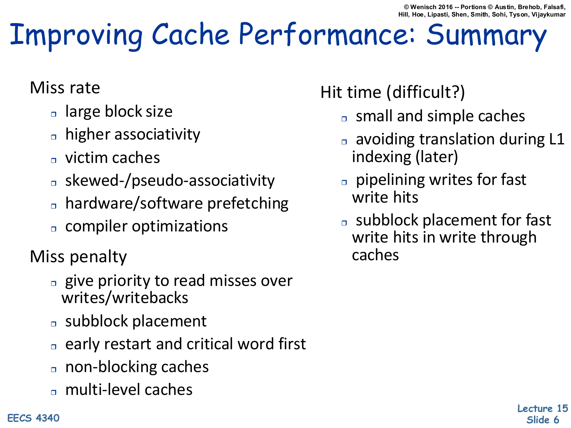
Miss rate
- large block size
- higher associativity
- victim caches
- skewed-/pseudo-associativity
- hardware/software prefetching
- compiler optimizations
Miss penalty
- give priority to read misses over writes/writebacks
- subblock placement
- early restart and critical word first
- non-blocking caches
- multi-level caches
Hit time (difficult?)
- small and simple caches
- avoiding translation during L1 indexing (later)
- pipelining writes for fast write hits
- subblock placement for fast write hits in write through caches
This is a wrap-up of the cache-optimization toolbox accumulated across L12–L14, organized by which term of AMAT = hit time+miss rate×miss penalty each technique attacks. Reducing miss rate uses larger blocks (better spatial locality up to a point), higher associativity (fewer conflict misses), victim and pseudo-associative caches, prefetching, and compiler-level layout/loop transformations. Reducing miss penalty overlaps misses with useful work: prioritize critical reads over background writebacks, use sub-block valid bits, restart the pipeline as soon as the requested word arrives (early restart / critical-word-first), allow misses to proceed in parallel (non-blocking lockup-free caches), and add levels (L2/L3). Reducing hit time is the hardest because L1 sits on the critical path: keep the L1 small and direct-mapped-ish, avoid the address-translation step in the indexing path (the bullet “later” — that’s exactly what the rest of this lecture builds toward with virtually-indexed caches), and pipeline writes through a store buffer.
Virtual Memory
2 Parts to Modern VM
Show slide text
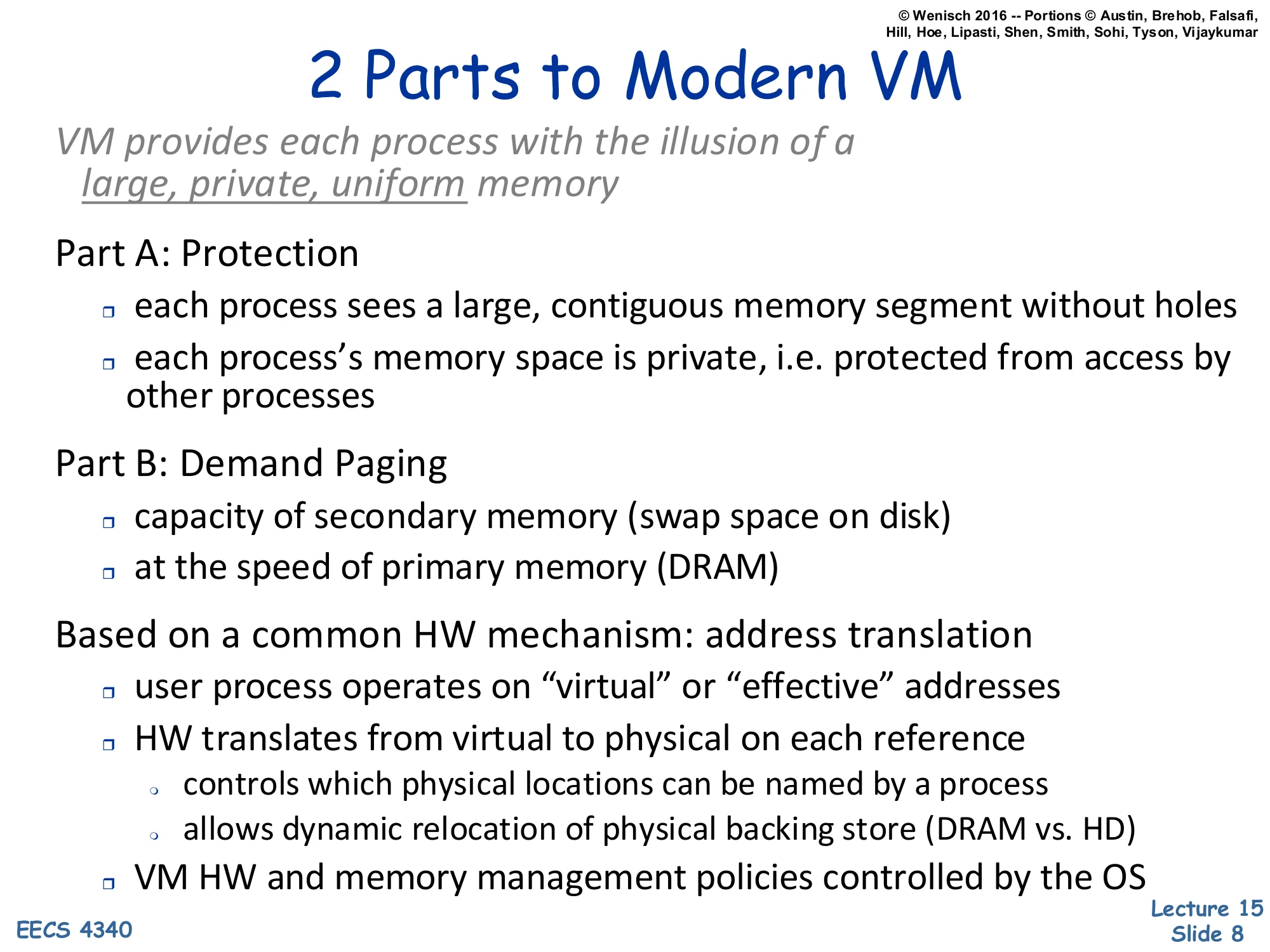
2 Parts to Modern VM
VM provides each process with the illusion of a large, private, uniform memory
Part A: Protection
- each process sees a large, contiguous memory segment without holes
- each process’s memory space is private, i.e. protected from access by other processes
Part B: Demand Paging
- capacity of secondary memory (swap space on disk)
- at the speed of primary memory (DRAM)
Based on a common HW mechanism: address translation
- user process operates on “virtual” or “effective” addresses
- HW translates from virtual to physical on each reference
- controls which physical locations can be named by a process
- allows dynamic relocation of physical backing store (DRAM vs. HD)
- VM HW and memory management policies controlled by the OS
This is the foundational slide of the lecture. Virtual memory does two distinct jobs that just happen to share one mechanism. Part A — protection gives every process an isolated address space: each program sees a flat, contiguous range starting at 0, with no holes punched out for the kernel or for other processes, and no ability to read or write another process’s memory. Part B — demand paging uses disk as a backing store so the working set in DRAM can be smaller than the program’s memory footprint; the hardware faults when a referenced page is not resident, the OS fetches it from swap, and execution resumes transparently. Both jobs are implemented with a single primitive: hardware address translation on every load and store. The user program emits virtual (a.k.a. effective) addresses; the MMU rewrites each one to a physical address before it reaches DRAM. Two consequences fall out: (1) the OS controls which physical frames a process can name (protection), and (2) the OS can relocate the physical backing for a virtual page at will — including moving it to disk — without the user program noticing (demand paging). The OS owns the policy; hardware enforces it.
Evolution of Protection Mechanisms
Show slide text
Evolution of Protection Mechanisms
Earliest machines had no concept of protection and address translation
- no need — single process, single user
- automatically “private and uniform” (but not very large)
- programs operated on physical addresses directly
- no multitasking protection, no dynamic relocation (at least not very easily)
Before virtual memory existed, a single program owned the entire physical address space, so privacy and uniformity were free — there was nobody else around to violate them. The downside is that the address space was bounded by however much DRAM was physically installed (“not very large”), and migrating from one physical layout to another required relinking or relocating the binary. Once timesharing arrived, two new requirements showed up that physical addressing cannot satisfy: (a) protection between concurrently resident processes, and (b) the ability to move a process’s pages around in physical memory after it has started running. The next slides walk through three increasingly sophisticated answers — base/bound registers, segmentation, and finally paging — that each addressed part of the problem before paged virtual memory subsumed all of them.
Base and bound registers
Show slide text
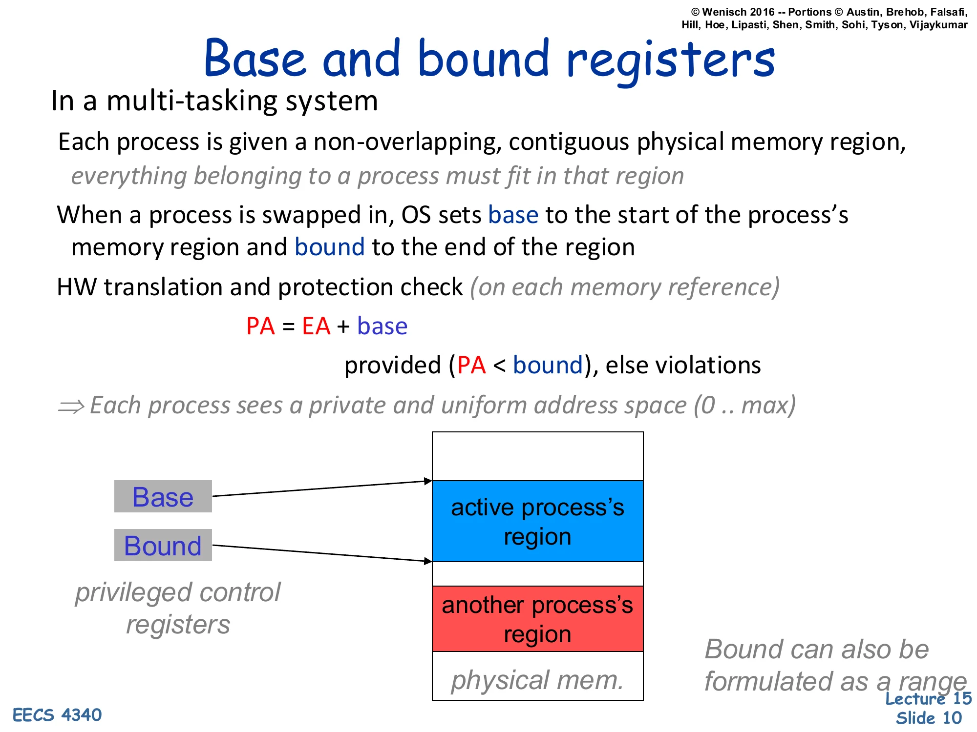
Base and bound registers
In a multi-tasking system
Each process is given a non-overlapping, contiguous physical memory region, everything belonging to a process must fit in that region
When a process is swapped in, OS sets base to the start of the process’s memory region and bound to the end of the region
HW translation and protection check (on each memory reference)
PA=EA+base
provided (PA<bound), else violations
⇒ Each process sees a private and uniform address space (0..max)
privileged control registers
Base and Bound point to the active process’s region in physical memory; another process’s region sits below.
Bound can also be formulated as a range
Base-and-bound registers are the simplest hardware mechanism that delivers a private address space. The OS gives each process one contiguous slab of physical DRAM, then loads two privileged registers on context switch: base (the slab’s starting physical address) and bound (its end). On every memory reference, hardware adds base to the effective address — that’s the entire translation — and traps if the result exceeds bound. From the program’s point of view it has a uniform [0,max] address space; the OS relocates that range anywhere in DRAM by editing two registers. The mechanism is fast and cheap, but it has two crippling limitations that paging will eventually fix. First, a process’s entire memory image must fit in a single contiguous physical region — there is no way to split heap from stack across a fragmented free pool. Second, growing a process requires either pre-reserving slack space inside its region or copying the whole image to a larger free slot. These limitations motivate the segmented and then the paged designs in the next slides.
Segmented Address Space
Show slide text
Segmented Address Space
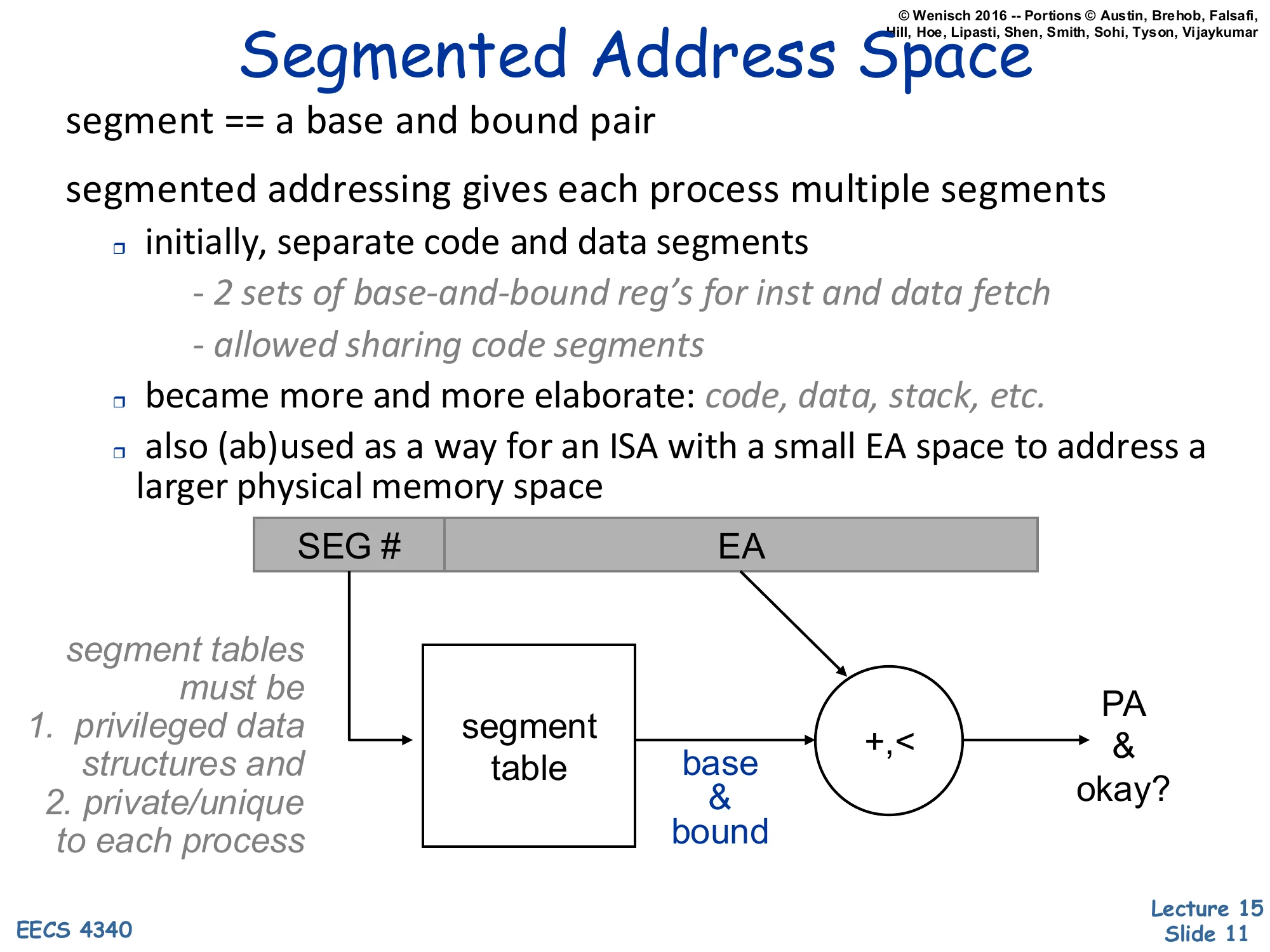
segment == a base and bound pair
segmented addressing gives each process multiple segments
- initially, separate code and data segments
- 2 sets of base-and-bound reg’s for inst and data fetch
- allowed sharing code segments
- became more and more elaborate: code, data, stack, etc.
- also (ab)used as a way for an ISA with a small EA space to address a larger physical memory space
Diagram: [SEG#∣EA]→ segment table indexed by SEG# returns (base,bound) pair, then +,< produces PA and an okay? signal.
segment tables must be
- privileged data structures and
- private/unique to each process
Segmented addressing generalizes base-and-bound from one slab per process to many. The effective address now carries an explicit segment selector that indexes a per-process segment table; the indexed entry is itself a (base, bound) pair, and the rest of the EA acts as the offset within that segment. Two early benefits: code and data could live in different physical regions (often with different protection — read-only for code), and several processes could share a single physical code segment by having its entry appear in each of their segment tables. The mechanism became more elaborate over time (separate segments for code, initialized data, stack, BSS) and was sometimes abused — Intel’s 8086 used segments mainly to extend a 16-bit effective-address space to a 20-bit physical-address space rather than for protection. Like base-and-bound, the segment table must be a privileged structure private to each process; the OS reloads its base register on context switch. The next slide explains why segmentation is still not enough.
Paged Address Space
Show slide text
Paged Address Space
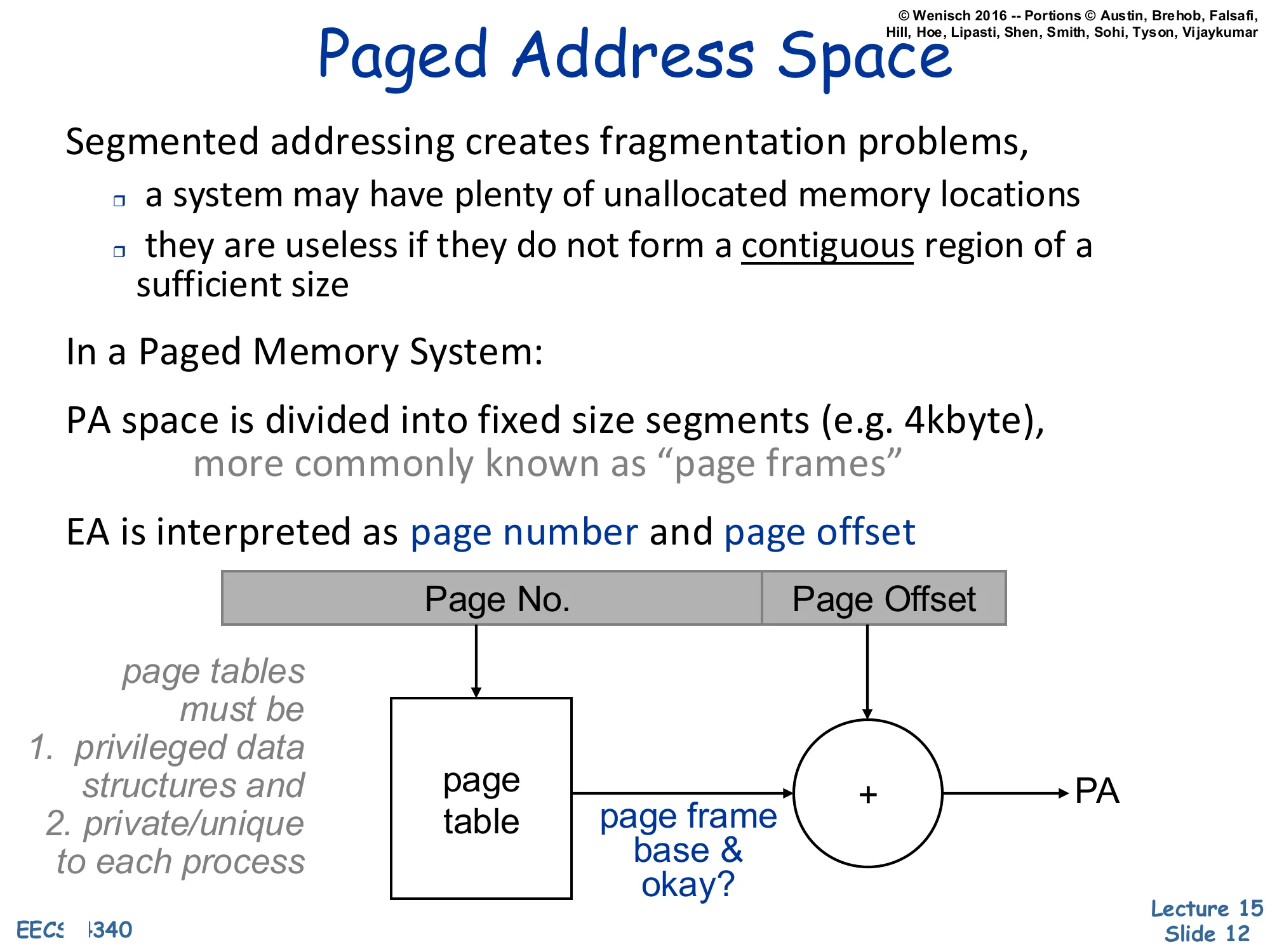
Segmented addressing creates fragmentation problems,
- a system may have plenty of unallocated memory locations
- they are useless if they do not form a contiguous region of a sufficient size
In a Paged Memory System:
PA space is divided into fixed size segments (e.g. 4kbyte), more commonly known as “page frames”
EA is interpreted as page number and page offset
Diagram: [Page No.∣Page Offset]→ page table indexed by page number returns page frame base & okay?, then + with offset produces PA.
page tables must be
- privileged data structures and
- private/unique to each process
Variable-sized segments suffer from external fragmentation: after segments come and go, free memory ends up scattered as small holes that cannot satisfy a large allocation even though their total size would. Paging fixes this by chopping physical memory into fixed-size frames (e.g. 4 KB) and chopping each virtual address space into matching-size pages. Any virtual page can map to any physical frame; the page table for the process records the mapping. Because every frame is the same size, free physical memory never fragments — the OS just keeps a free list of frames and grabs any one when a new page is allocated. The effective address is split into a high Page No. field that indexes the page table and a low Page Offset field that is concatenated unchanged onto the looked-up page-frame base to form the physical address (the diagram draws this as + but it is logically a concatenation when page sizes are powers of two). The page table is once again a privileged, per-process structure pointed to by a hardware base register the OS reloads on context switch.
Demand Paging
Show slide text
Demand Paging
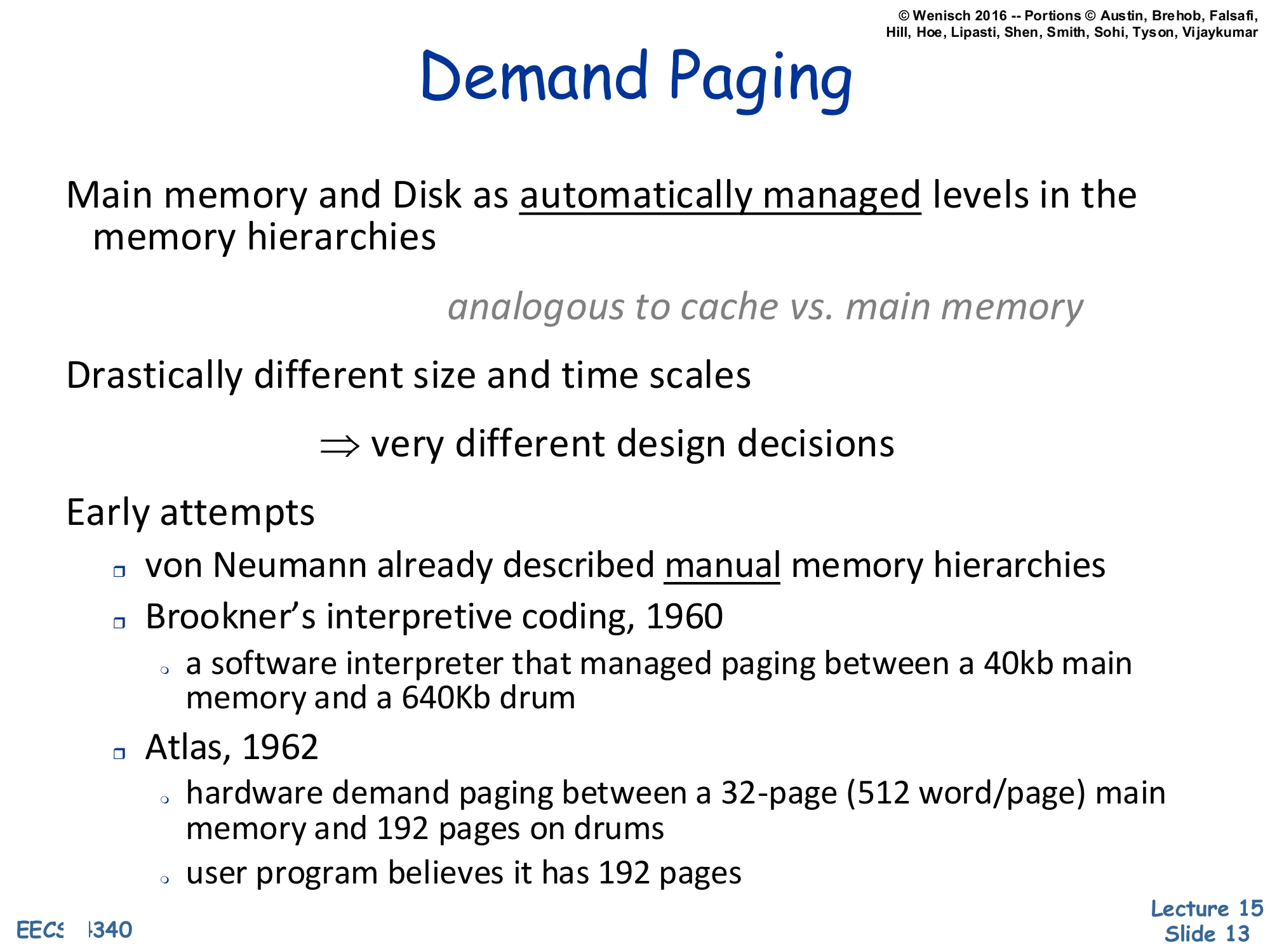
Main memory and Disk as automatically managed levels in the memory hierarchies
analogous to cache vs. main memory
Drastically different size and time scales
⇒ very different design decisions
Early attempts
- von Neumann already described manual memory hierarchies
- Brookner’s interpretive coding, 1960
- a software interpreter that managed paging between a 40kb main memory and a 640Kb drum
- Atlas, 1962
- hardware demand paging between a 32-page (512 word/page) main memory and 192 pages on drums
- user program believes it has 192 pages
Demand paging reuses the cache idea — keep a hot working set in fast memory, evict cold lines to slow memory — but applies it between DRAM and disk instead of between SRAM and DRAM. The mechanism is the same (resident vs. non-resident, replacement on miss, write-back of dirty data) but the constants are wildly different. DRAM is megabytes-to-gigabytes; disk is gigabytes-to-terabytes. A cache miss costs hundreds of cycles; a page fault costs millions. That gap forces different design points: page sizes are kilobytes (not 64 bytes), miss handling is in software (the OS handles a page fault), and replacement policies can afford to be much more sophisticated because the per-decision time budget is so large. The historical bullets put the idea in context: von Neumann described manual memory hierarchies in the original IAS reports, the 1960 Brookner system implemented paging in software via an interpreter, and the 1962 Manchester Atlas was the first machine with hardware demand paging — its 32 resident frames gave the user the illusion of 192 pages, exactly the modern model.
Demand Paging vs. Caching: 2016
Show slide text
Demand Paging vs. Caching: 2016
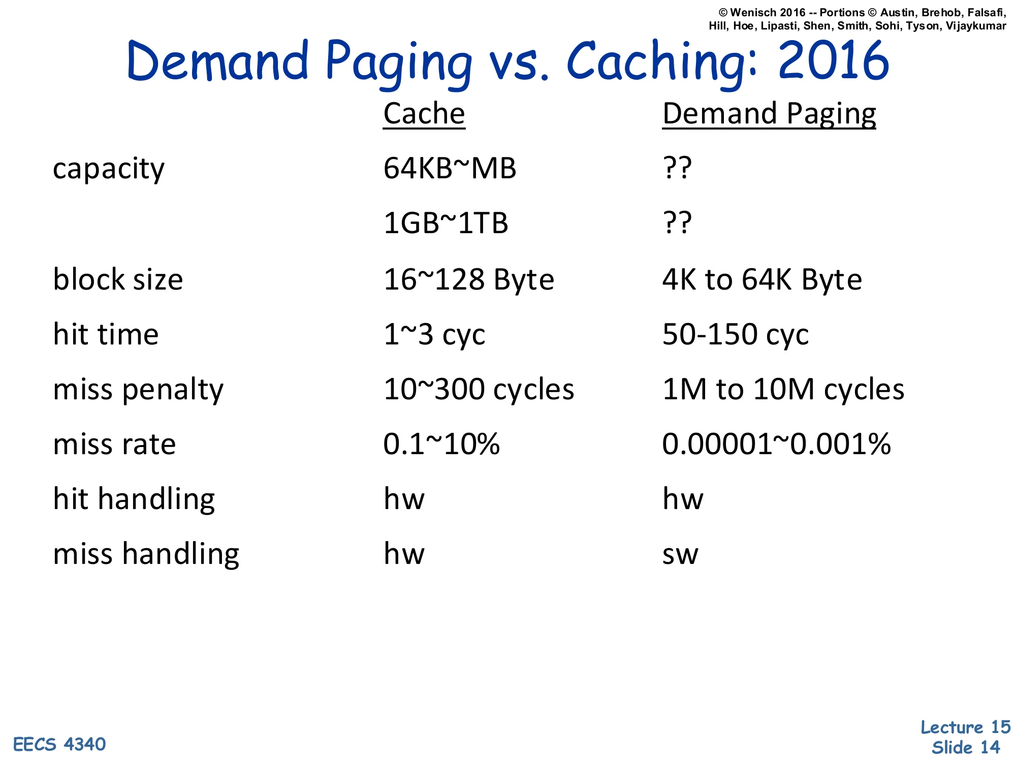
| Cache | Demand Paging | |
|---|---|---|
| capacity | 64KB | ?? / ?? |
| block size | 16~128 Byte | 4K to 64K Byte |
| hit time | 1~3 cyc | 50–150 cyc |
| miss penalty | 10~300 cycles | 1M to 10M cycles |
| miss rate | 0.1~10% | 0.00001~0.001% |
| hit handling | hw | hw |
| miss handling | hw | sw |
The numerical comparison drives home why demand paging needs a fundamentally different design from a hardware cache, even though both are “keep the hot stuff close” hierarchies. The capacity gap is roughly 1000× (MB vs GB) and the latency gap is even larger: DRAM hit takes 50–150 cycles while a page fault to disk costs 106–107 cycles — five orders of magnitude. That ratio dictates several design choices listed elsewhere in the lecture: (1) blocks are much bigger (4–64 KB pages vs 64 B cache lines) because amortizing a multi-million-cycle miss over a small block is wasteful; (2) the miss rate must be made tiny (10−5) because the miss penalty is so catastrophic; (3) miss handling is done in software (the OS page-fault handler) because the millions of cycles available let software inspect, log, and decide replacement with no measurable cost. Hits, in contrast, are handled by hardware on both sides — paying 106 cycles per hit would defeat the whole hierarchy.
Page-Based Virtual Memory
Show slide text
Page-Based Virtual Memory
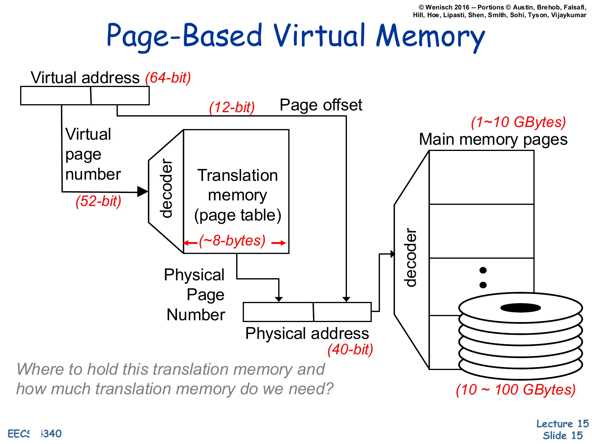
Virtual address (64-bit) split into Virtual Page Number (52-bit) and Page Offset (12-bit).
The VPN feeds a decoder into a Translation memory (page table); each entry is ~8 bytes.
Lookup yields the Physical Page Number, which is concatenated with the page offset to form the Physical address (40-bit).
A decoder on the physical address selects among Main memory pages (1–10 GBytes) backed by disk (10–100 GBytes).
Where to hold this translation memory and how much translation memory do we need?
This is the canonical page-based virtual memory picture with concrete bit widths. A 64-bit virtual address splits into a 52-bit virtual page number (VPN) and a 12-bit page offset — implying a 212=4 KB page size. The VPN indexes the page table (each entry is ~8 bytes — a 64-bit physical address plus permission and status bits) to look up the 28-bit physical page number (PPN). The PPN is concatenated with the 12-bit offset to form the 40-bit physical address that addresses the 240=1 TB physical address space. The page table itself lives in main memory and is backed by disk. The slide closes with the question that motivates the next several slides: a flat 252-entry page table with 8 B entries would be 255 bytes — vastly more than physical memory! So the table must be stored and organized cleverly. Hierarchical and inverted page tables, plus the TLB for caching translations, are the answer.
Page table organization
Hierarchical Page Table
Show slide text
Hierarchical Page Table
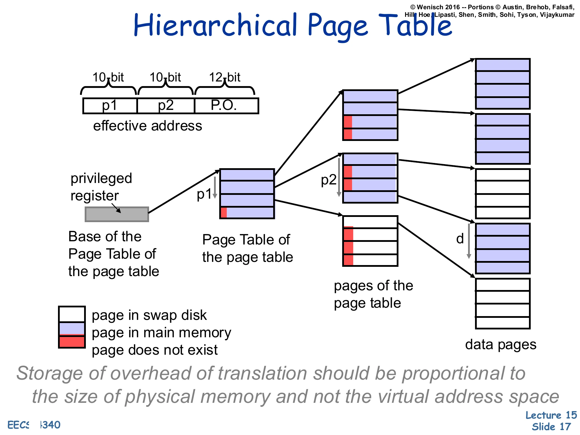
Effective address split: [p1(10 bit)∣p2(10 bit)∣P.O.(12 bit)]
A privileged register points to the Base of the Page Table of the page table (root). p1 indexes the root table, returning either a pointer to a second-level Page Table of the page table node or a marker (page in swap disk / page in main memory / page does not exist).
p2 then indexes the second-level pages of the page table to return the data-page descriptor; combined with the page offset d it locates the data pages.
Storage of overhead of translation should be proportional to the size of physical memory and not the virtual address space.
Hierarchical (multi-level / radix) page tables solve the size problem on the previous slide by storing the page table itself paged. The VPN is broken into multiple fields — here p1 and p2, each 10 bits — which index successive levels of the radix tree. A single privileged register holds the root, exactly like CR3 on x86. Most virtual address space is unused in any real process (a 64-bit process rarely uses the full 252 pages), so most root entries point to nothing — “page does not exist” — and the corresponding subtree consumes zero physical memory. Subtrees that do exist may themselves be paged out: an entry can mean “this page-table page is in main memory,” “this page-table page is on swap,” or “this entry is unused.” The key property is captured in the italicized invariant on the slide: translation overhead is now proportional to the resident working set, not the (much larger) virtual address space. The cost is an extra memory reference per level on each TLB miss, which is exactly why the TLB matters so much.
Inverted or Hashed Page Tables
Show slide text
Inverted or Hashed Page Tables
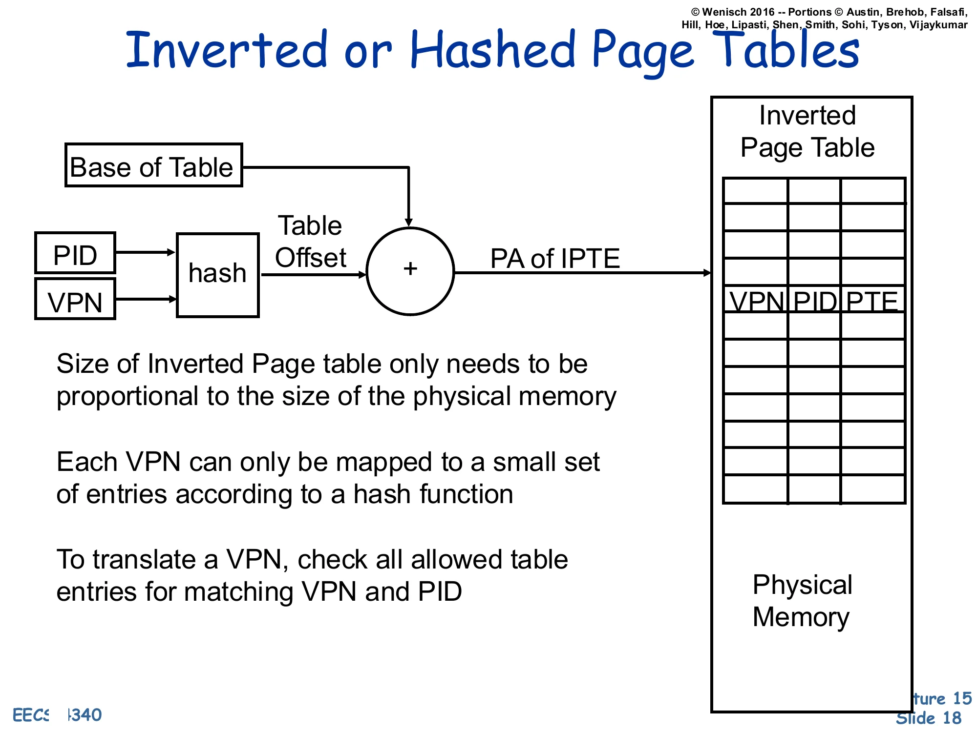
(PID, VPN)→hash→Table Offset, then +Base of Table=PA of IPTE, which indexes the Inverted Page Table whose entries hold ⟨VPN,PID,PTE⟩. The Inverted Page Table sits in physical memory.
- Size of Inverted Page table only needs to be proportional to the size of the physical memory
- Each VPN can only be mapped to a small set of entries according to a hash function
- To translate a VPN, check all allowed table entries for matching VPN and PID
An inverted page table flips the indexing direction. Instead of one entry per virtual page, it has one entry per physical frame, holding the (VPN, PID, PTE) tuple of whichever process currently owns that frame. Translation hashes the (PID, VPN) pair into a small set of candidate entries; hardware (or the TLB-miss handler) walks those entries and matches on VPN and PID. The structural benefit is exactly the goal stated on slide 17: table size grows with physical memory, not with virtual address space — even a process with a sparse, huge virtual layout occupies at most one entry per resident frame. The drawback is sharing: when two processes map the same physical frame, the table can hold only one entry per frame, so shared pages need extra mechanism (chains, separate sharing tables). Inverted page tables were used by PowerPC and IA-64; modern x86 and ARM use hierarchical tables instead.
Virtual-to-Physical Translation
Translation Look-aside Buffer (TLB)
Show slide text
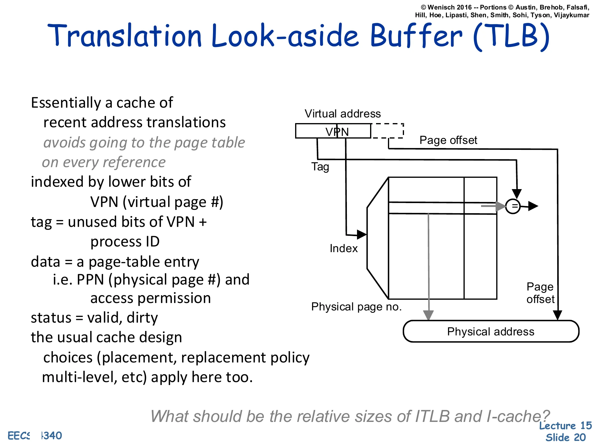
Translation Look-aside Buffer (TLB)
Essentially a cache of recent address translations avoids going to the page table on every reference
- indexed by lower bits of VPN (virtual page #)
- tag = unused bits of VPN + process ID
- data = a page-table entry, i.e. PPN (physical page #) and access permission
- status = valid, dirty
- the usual cache design choices (placement, replacement policy, multi-level, etc.) apply here too
Diagram: Virtual address [VPN∣Page offset]. The lower bits of the VPN form the Index into the TLB; the upper bits form the Tag that is compared against the stored tag. A hit returns the Physical page no., which is concatenated with the Page offset to form the Physical address.
What should be the relative sizes of ITLB and I-cache?
The Translation Lookaside Buffer is just a regular cache whose lines hold page-table entries instead of memory data. Each entry maps a VPN+PID to a PPN plus permission/status bits (valid, dirty, R/W/X). On every load, store, and instruction fetch, the MMU looks up the VPN in the TLB. A hit is essentially free (≤ 1 cycle) and produces the PPN immediately. A miss triggers a page-table walk — done by hardware (x86, ARM) or by software (early MIPS, Alpha) — that reloads the missing translation. Because it is just a cache, every cache-design choice from L12–L13 reappears: associativity, replacement policy, multi-level (L1 ITLB + L1 DTLB + L2 TLB on modern x86), inclusion, and so on. The closing question — relative sizes of ITLB vs. I-cache — is a pointed reminder that one TLB entry covers an entire 4 KB page, so a small TLB (e.g., 64 entries × 4 KB = 256 KB of code reach) typically covers many times more bytes than the I-cache itself.
Virtual to Physical Address Translation
Show slide text
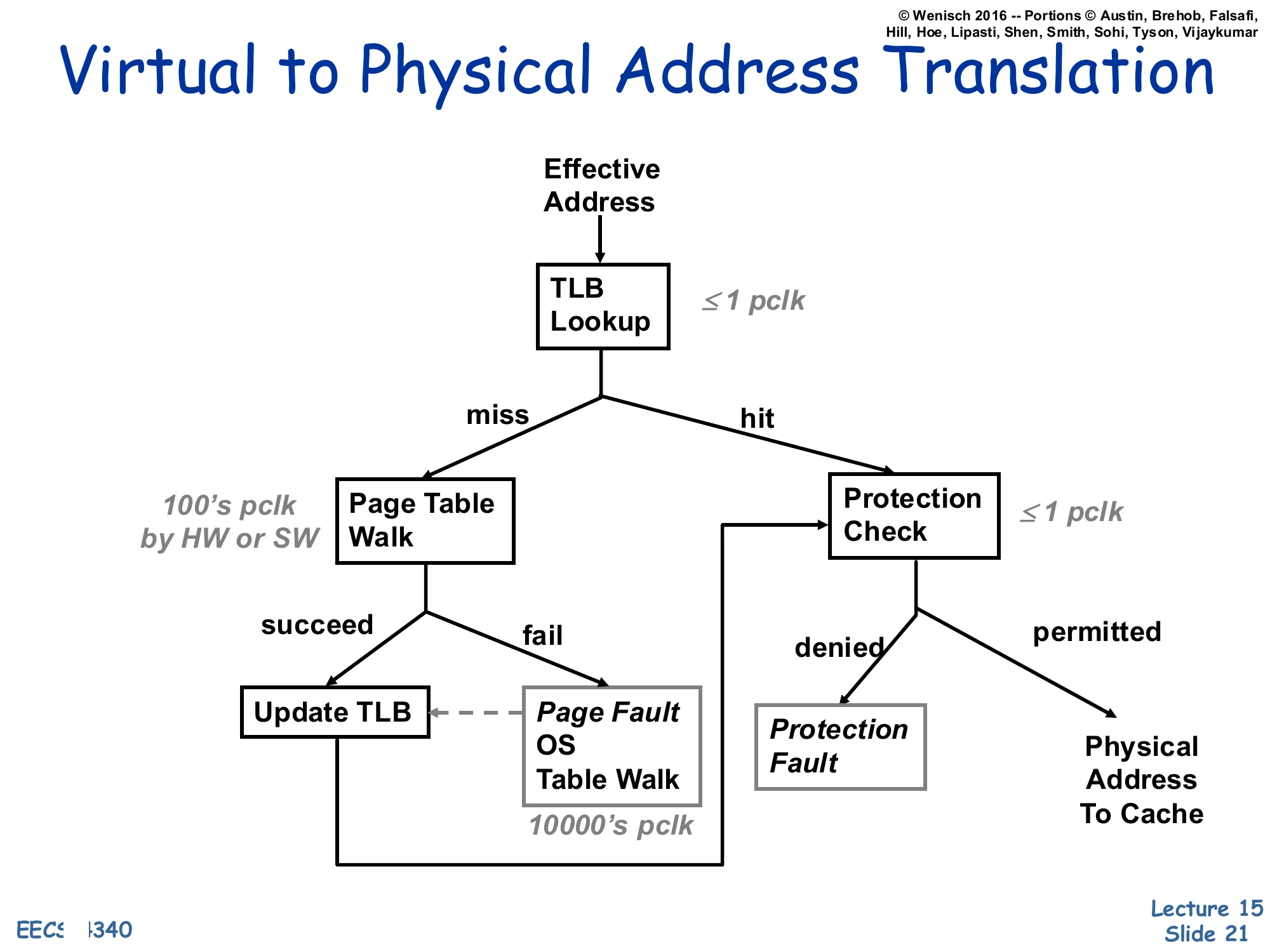
Virtual to Physical Address Translation
Flow on each Effective Address:
- TLB Lookup (≤1 pclk)
- On hit → Protection Check (≤1 pclk)
- permitted → Physical Address To Cache
- denied → Protection Fault
- On miss → Page Table Walk (100’s pclk by HW or SW)
- succeed → Update TLB → Protection Check (flow continues)
- fail → Page Fault: OS Table Walk (10000’s pclk), which then services the fault and updates the TLB
This flow chart is the single most important diagram in the lecture. Three latency tiers stack vertically: a TLB hit is nearly free (≤1 processor clock); a TLB miss that resolves with a page-table walk in hardware costs hundreds of clocks; a true page fault (the page is not even in DRAM) costs tens of thousands of clocks because the OS must read the page back from disk. After the translation succeeds, a protection check runs against the PTE’s permission bits — denial raises a protection fault rather than a page fault, because the translation existed but the access was illegal (e.g., a store to a read-only page or a user access to a kernel page). This is the diagram you should be able to redraw on an exam: TLB hit/miss → walk succeed/fail → protection permitted/denied, with the three latency labels pinned to the right edges.
Cache Placement and Address Translation
Show slide text
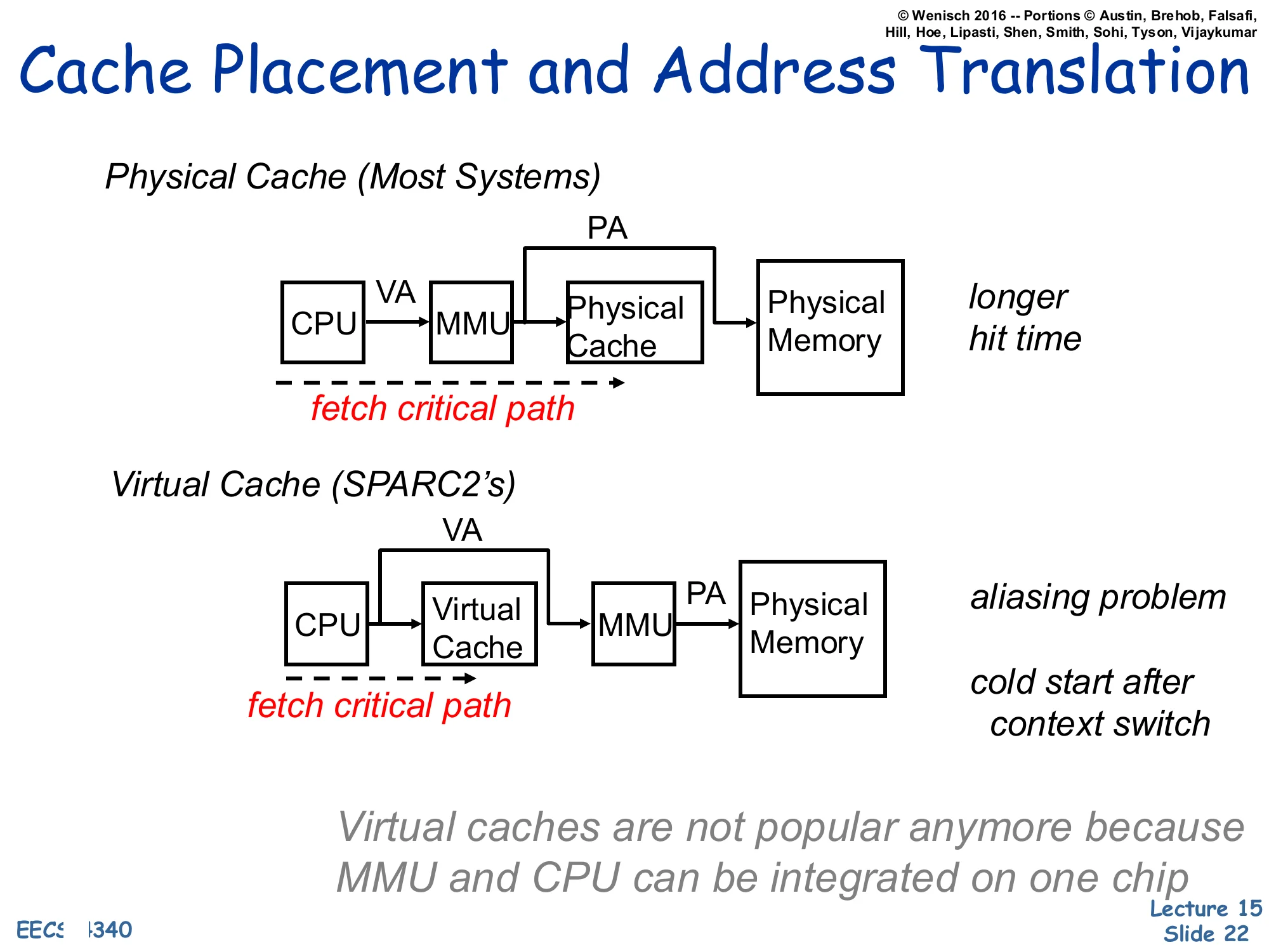
Cache Placement and Address Translation
Physical Cache (Most Systems)
CPUVAMMUPAPhysical Cache→Physical Memory
fetch critical path runs through CPU, MMU, and Physical Cache.
→ longer hit time
Virtual Cache (SPARC2’s)
CPUVAVirtual CacheVAMMUPAPhysical Memory
fetch critical path runs through CPU and Virtual Cache before reaching the MMU.
→ aliasing problem → cold start after context switch
Virtual caches are not popular anymore because MMU and CPU can be integrated on one chip
Where we place the MMU relative to the cache picks the central tradeoff of this lecture. A physical cache translates first, then looks up — the cache sees only physical addresses, so context switches and synonyms are non-issues, but the TLB now sits on the L1 hit critical path and lengthens the cycle. A virtual cache indexes and tags entirely in the virtual address space, so the TLB is consulted only on a miss; this is fast, but two problems appear. First, aliasing/synonyms — two virtual addresses that map to the same physical address can occupy two different cache lines, causing visibility bugs after writes. Second, cold start on context switch — virtual tags are meaningless to the new process, so the cache must be flushed (or process-tagged) on every context switch. The slide notes that virtual caches were used in machines like the SPARC2 but are no longer popular, partly because tightly integrating the MMU and CPU on the same die has shrunk the TLB latency enough that physical caches no longer cost a cycle. The next several slides develop a hybrid — virtually-indexed, physically-tagged — that keeps the speed of virtual indexing without the synonym problem.
Physically Indexed Cache
Show slide text
Physically Indexed Cache
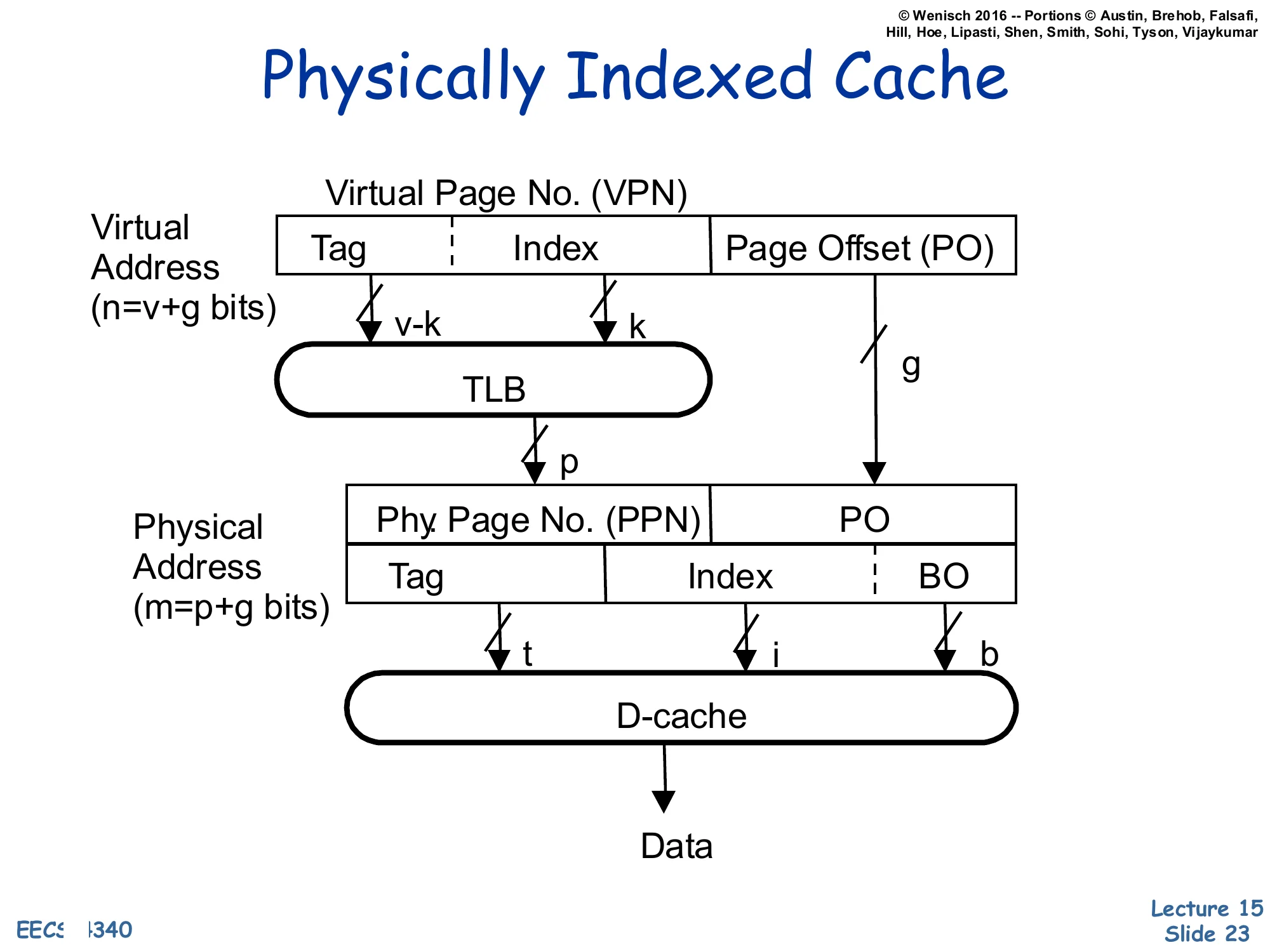
Virtual Address (n=v+g bits): [Tag∣Index∣Page Offset (PO)] where the VPN field is v bits (v−k tag, k index) and the page offset is g bits.
The full VPN (v bits) goes through the TLB to produce the Physical Page No. (PPN), p bits.
Physical Address (m=p+g bits): [PPN∣PO] is then re-split as [Tag(t)∣Index(i)∣BO(b)] for the D-cache, which returns Data.
A Physically-Indexed, Physically-Tagged (PIPT) cache is the simplest and safest design: the TLB translates the virtual address to a physical one first, and the cache uses bits from the physical address for both the index and the tag. Because the tag is physical, there are no synonyms: a given physical block has exactly one home set and one tag, no matter how many virtual addresses point at it. Because the index is physical, the index field can be as wide as you like and the cache can be as large as you like without aliasing constraints. The price is that the L1 hit latency includes the TLB lookup serially: TLB → cache index → tag compare → data, which is the longer critical path the previous slide warned about. The next slide shows how to overlap the two.
Virtually Indexed Cache — Parallel Access to TLB and Cache
Show slide text
Virtually Indexed Cache
Parallel Access to TLB and Cache arrays
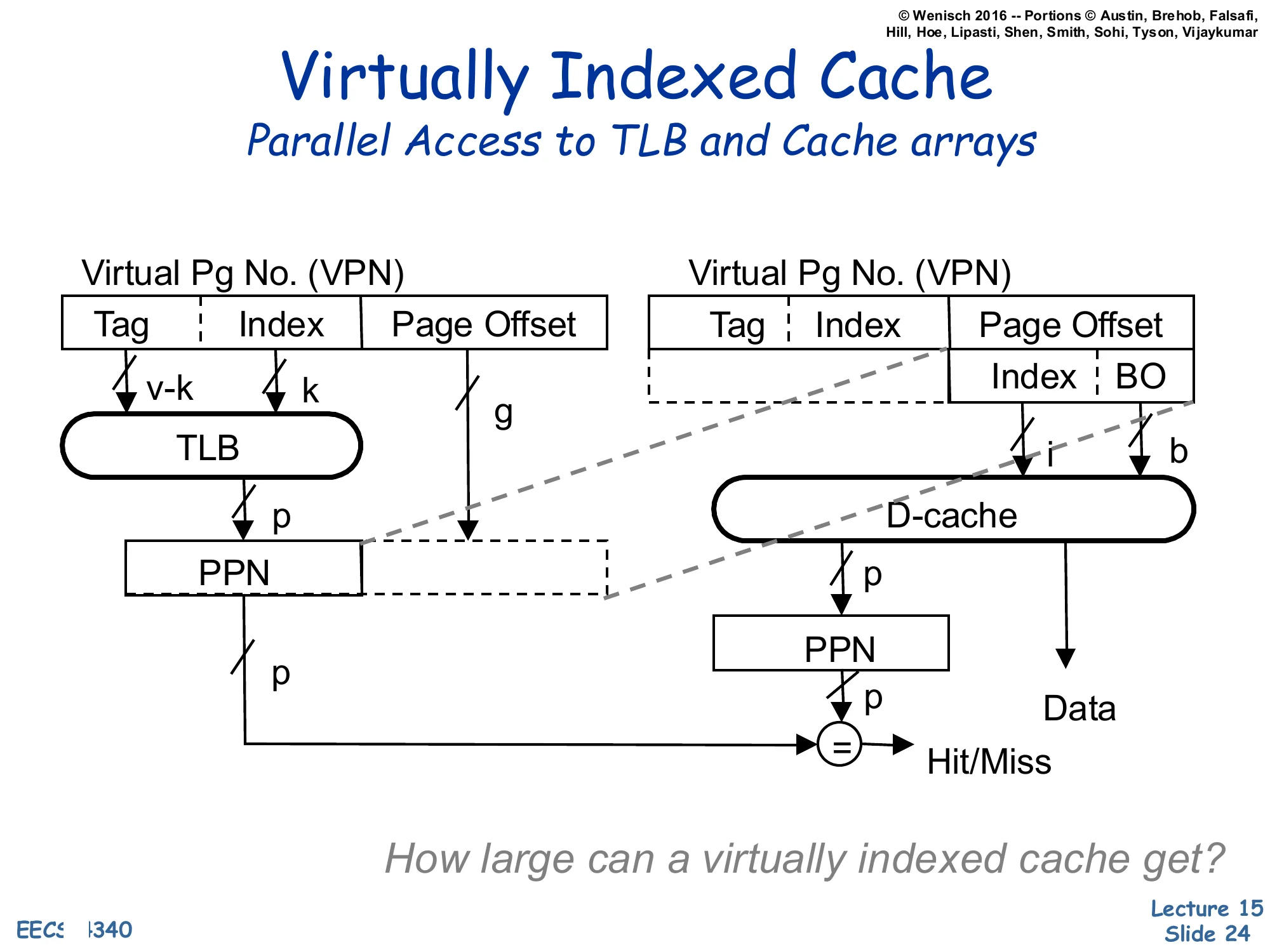
Left path: VPN [Tag∣Index] + Page Offset → TLB produces PPN(p).
Right path: in parallel, the lower bits of the virtual address — taken entirely from the Page Offset — provide the cache Index (i) and BO (b) to the D-cache, which returns the candidate Data and a stored PPN tag.
The TLB-supplied PPN is then compared with the cache’s stored PPN tag (=) to produce Hit/Miss.
How large can a virtually indexed cache get?
This is the Virtually-Indexed, Physically-Tagged (VIPT) design that almost every modern L1 uses. Trick: take the index bits entirely from the page offset. The page offset is identical in the virtual and physical address (translation only changes the page-number bits), so indexing with offset bits is equivalent to physical indexing — no aliasing — yet it requires no TLB lookup and can run in parallel with the TLB. The TLB and cache arrays both fire on the same cycle; when the TLB returns the PPN it is compared against the physically-stored tag to confirm hit/miss. The effect is a PIPT-correctness, virtual-cache-speed L1. The closing question — how large can a virtually indexed cache get? — asks for the constraint: index bits must fit inside the page offset, so cache size≤page size×associativity. With 4 KB pages and 8-way associativity the maximum is 32 KB, which is exactly the L1 size used by Intel and AMD for two decades.
Large Virtually Indexed Cache
Show slide text
Large Virtually Indexed Cache
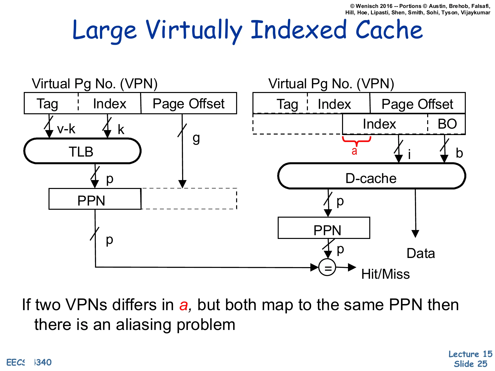
Same structure as the parallel VIPT cache, but the cache index now extends above the page offset — the highlighted slice a comes from the VPN portion of the virtual address rather than from the page offset.
Left: VPN [Tag∣Index]→ TLB → PPN (p).
Right: D-cache index (i) now includes the bits a that overlap into the VPN; the cache returns Data and a stored PPN, which is compared to the TLB-supplied PPN at = for Hit/Miss.
If two VPNs differ in a, but both map to the same PPN then there is an aliasing problem.
Once the VIPT cache size grows beyond page size×associativity, the index field has to extend into the VPN bits — labelled a on the diagram. Those extra index bits can differ between two virtual addresses that translate to the same physical address (the OS chose different VPNs for the same PPN), so the same physical block may now sit in two different cache sets. That is the aliasing/synonym problem reborn: a write to one virtual alias does not update the other alias, and a later read of the second alias will see stale data. The next two slides develop the synonym story explicitly and the slides after them survey four solutions, including the MIPS R10K’s L2-mediated approach.
Virtual Address Synonyms
Show slide text
Virtual Address Synonyms
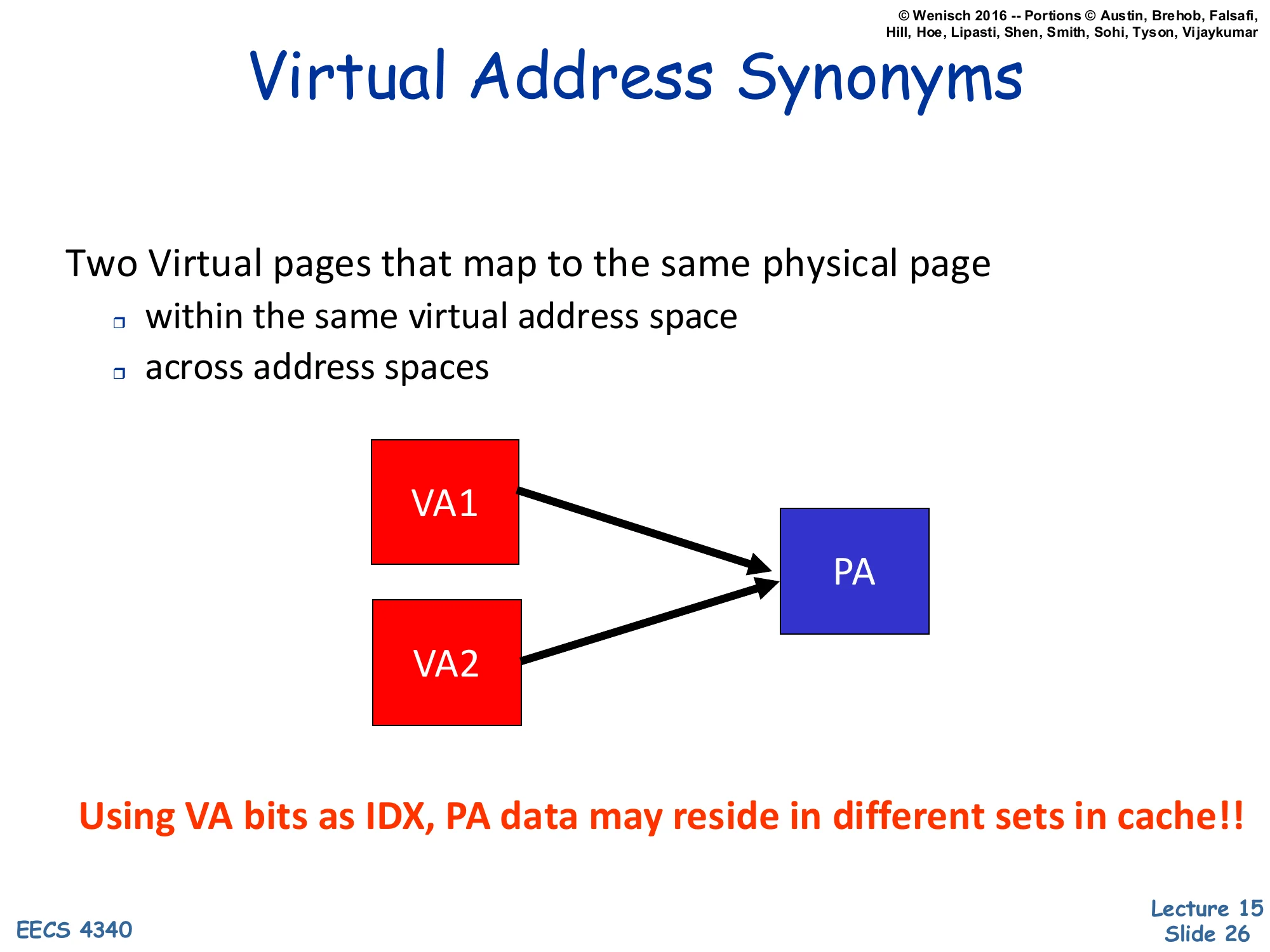
Two Virtual pages that map to the same physical page
- within the same virtual address space
- across address spaces
Diagram: VA1 and VA2 (red) both arrow to the same PA (blue).
Using VA bits as IDX, PA data may reside in different sets in cache!!
Synonyms (also called aliases) are pairs of virtual addresses that translate to the same physical address. They arise naturally in two contexts: (1) within one process, when the process maps the same file or shared-memory region at two virtual offsets, and (2) across processes, when two processes share a code page or a shared library by mapping the same physical frame into both their address spaces. Either way, when the cache index is partly derived from the VPN (as in the large-VIPT design), VA1 and VA2 can land in different cache sets — meaning the same physical line has two cache homes. A write to one alias updates one set; a subsequent read of the other alias misses the updated set and returns stale data. The bold red sentence on the slide captures the bug succinctly: physical data can reside in different sets when the index uses virtual bits. This is the aliasing problem the next slides will solve.
Synonym (or Aliasing)
Show slide text
Synonym (or Aliasing)
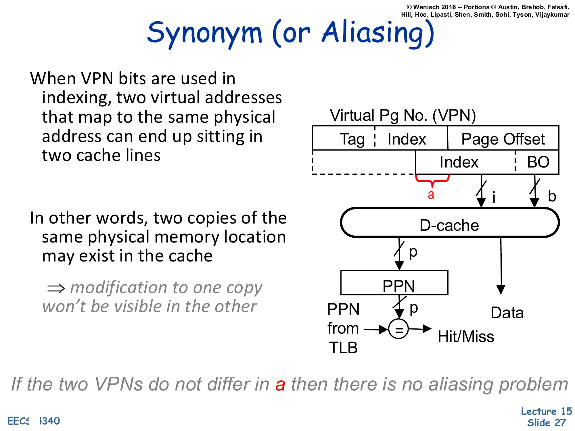
When VPN bits are used in indexing, two virtual addresses that map to the same physical address can end up sitting in two cache lines.
In other words, two copies of the same physical memory location may exist in the cache
⇒ modification to one copy won’t be visible in the other
Diagram: large-VIPT cache. The slice a of the VPN bleeds into the index i. The cache returns Data and a PPN that is compared with the PPN supplied by the TLB to determine Hit/Miss.
If the two VPNs do not differ in a then there is no aliasing problem
This restates the aliasing hazard introduced two slides earlier and pinpoints the exact bit field that causes it: the slice a where the cache index reaches above the page offset into the VPN. If two synonyms happen to share the same value of a — accidentally or by OS arrangement — they fall into the same cache set and aliasing disappears, because the cache’s tag comparison (using the TLB-supplied PPN) deduplicates them. If they differ in a, both copies can live in the cache simultaneously and writes to one will not propagate to the other. The italicized closing phrase telegraphs page coloring (one of the solutions on the next slide): if the OS allocates pages so that virtual and physical addresses agree in the index bits (VA[a]=PA[a]), the synonym condition cannot arise and the hazard is eliminated by software policy.
Synonym Solutions
Show slide text
Synonym Solutions
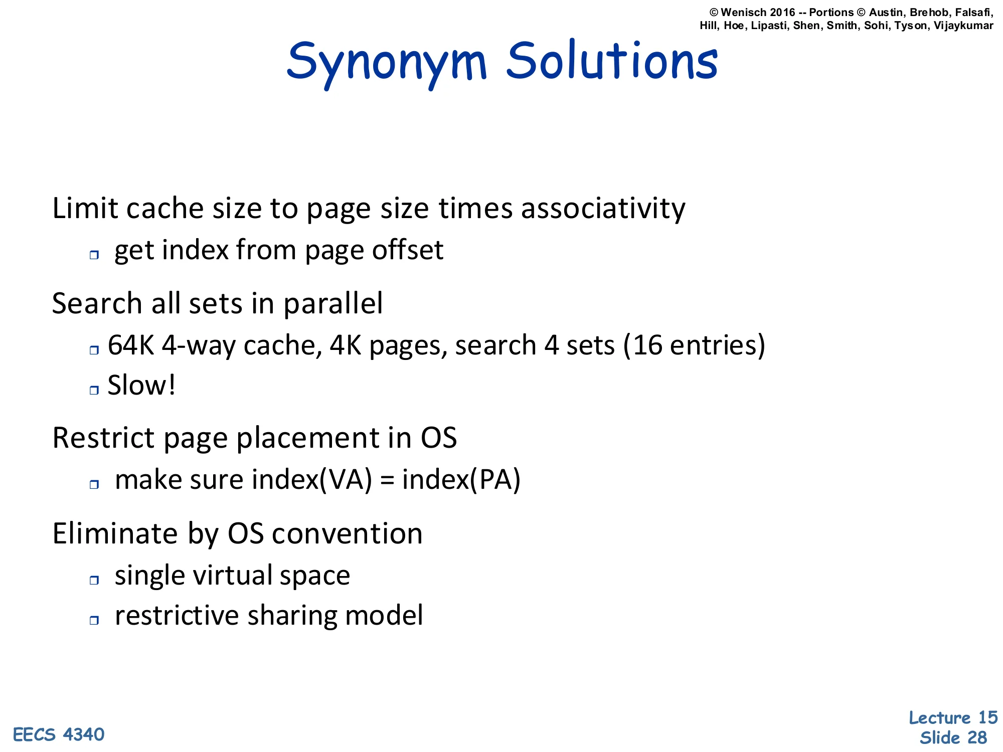
- Limit cache size to page size times associativity
- get index from page offset
- Search all sets in parallel
- 64K 4-way cache, 4K pages, search 4 sets (16 entries)
- Slow!
- Restrict page placement in OS
- make sure index(VA)=index(PA)
- Eliminate by OS convention
- single virtual space
- restrictive sharing model
Four cures for the synonym problem, in roughly increasing implementation effort:
- Cap the cache. Keep cache size ≤ page size × associativity so the entire index fits in the page offset. The clean VIPT design from slide 24. Easy, but caps L1 at e.g. 32 KB for 4 KB pages and 8-way.
- Search every possible alias set. For a 64 KB / 4-way / 4 KB-page cache, two index bits come from the VPN, so an alias might live in any of 22=4 sets — search all 16 entries on every access. Correct but slow.
- Page coloring (OS policy). When the OS allocates a physical page, it ensures the new PPN agrees with the VPN on the index bits (index(VA)=index(PA)). Aliases then fall in the same set and the hardware tag-compare catches them. Common in MIPS and SPARC.
- Outlaw aliases. Use a single global virtual address space, or forbid arbitrary
mmap-style sharing — viable only in research / niche systems.
The MIPS R10K on the next slide combines (1)+(3)+L2-mediated detection.
MIPS R10K Synonym Solution
Show slide text
MIPS R10K Synonym Solution
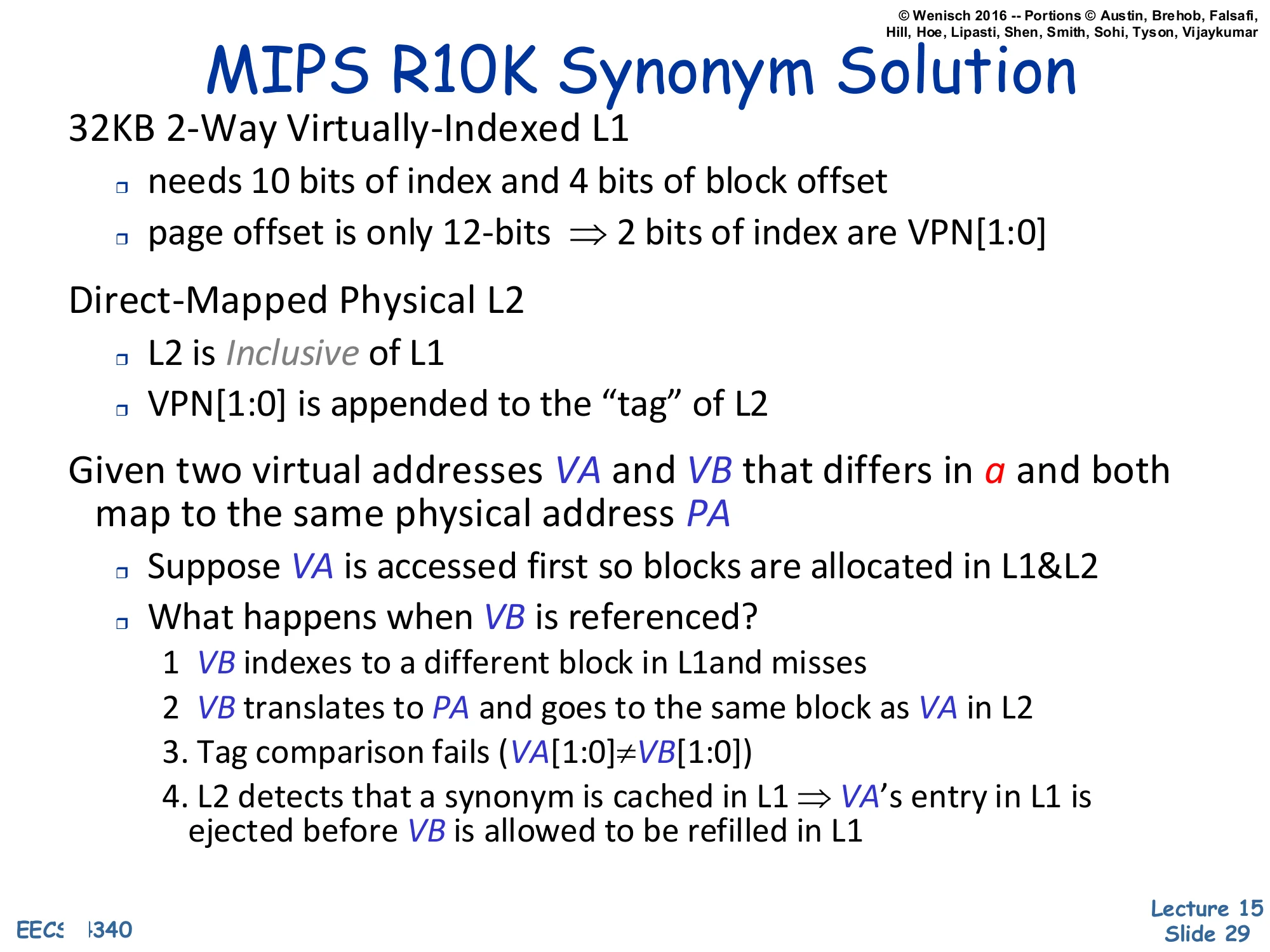
32KB 2-Way Virtually-Indexed L1
- needs 10 bits of index and 4 bits of block offset
- page offset is only 12-bits ⇒ 2 bits of index are VPN[1:0]
Direct-Mapped Physical L2
- L2 is Inclusive of L1
- VPN[1:0] is appended to the “tag” of L2
Given two virtual addresses VA and VB that differs in a and both map to the same physical address PA
- Suppose VA is accessed first so blocks are allocated in L1&L2
- What happens when VB is referenced?
- VB indexes to a different block in L1 and misses
- VB translates to PA and goes to the same block as VA in L2
- Tag comparison fails (VA[1:0]=VB[1:0])
- L2 detects that a synonym is cached in L1 ⇒ VA‘s entry in L1 is ejected before VB is allowed to be refilled in L1
The MIPS R10K’s solution is a beautiful piece of L1/L2 cooperation. Its 32 KB 2-way L1 needs 10 index bits and 4 offset bits, so 10+4=14 bits of address are below the L1 tag — but the page offset is only 12 bits, so two of the L1 index bits (VPN[1:0]) come from the VPN. That makes synonyms possible. The R10K augments the physically-indexed, direct-mapped L2 to remember which VPN bits the L1 used: VPN[1:0] is appended to the L2 tag, so the L2 effectively records which alias is currently cached in L1. Inclusion guarantees every L1 line is also in L2. The trace on the slide walks through what happens on a synonym: VB misses in L1 (because its VPN[1:0] differs from VA’s), translates to the same PA in L2, and the L2 tag compare fails on the appended VPN bits. That mismatch is the cue: L2 knows a synonym is currently resident in L1, so it forces L1 to evict VA’s line before refilling VB. At any moment, only one of VA/VB lives in L1 — invariant restored. This is option (3) from the previous slide implemented in hardware rather than in OS policy. The slide is a good example of how aliasing is solved by making L2 the global serialization point for translations.
Virtually Indexed Physically Tagged Cache
Show slide text
Virtually Indexed Physically Tagged Cache
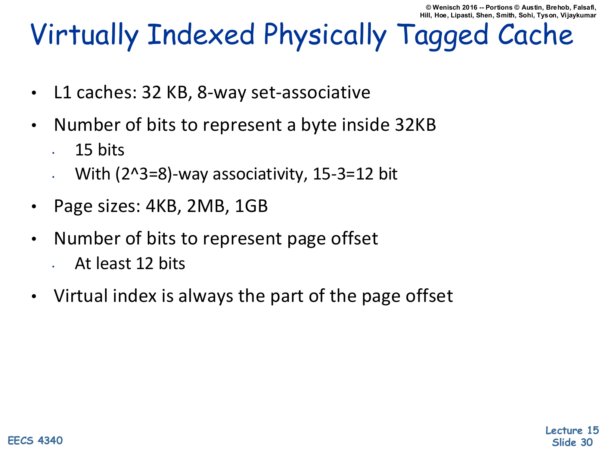
- L1 caches: 32 KB, 8-way set-associative
- Number of bits to represent a byte inside 32KB
- 15 bits
- With (23=8)-way associativity, 15−3=12 bit
- Page sizes: 4KB, 2MB, 1GB
- Number of bits to represent page offset
- At least 12 bits
- Virtual index is always the part of the page offset
A worked example that justifies the standard modern L1 sizing. A 32 KB cache addresses 215=32768 bytes, so 15 address bits live below the cache tag. With 8-way associativity the way selector consumes log28=3 of those bits, leaving 15−3=12 bits for the cache index plus block offset. The smallest supported page size is 4 KB = 212 B, so the page offset is exactly 12 bits — meaning the entire 12-bit cache index+offset region fits inside the page offset. Therefore the virtually-indexed cache index is a subset of the page offset, which is identical in virtual and physical addresses, so synonyms cannot occur. Larger pages (2 MB, 1 GB) only enlarge the page offset and trivially preserve the inclusion. This is exactly why 32 KB / 8-way L1 has been the canonical Intel and AMD L1 size for two decades — it is the largest VIPT design that is alias-free given the standard 4 KB minimum page.
Readings
Show slide text
Readings
For today:
- Appendix L, http://www.cs.yale.edu/homes/abhishek/abhishek-appendix-l.pdf
- Architectural and Operating System Support for Virtual Memory, https://doi.org/10.1007/978-3-031-01757-5
Announcements

Show slide text
Announcements
- Project #4
- Due: May 1, 11:59 PM Eastern Time
- Office hours
- End this week
- Final project presentation
- May 4, 2026
- 8:40 to 9:50 AM
- 8 minutes per group with 2 minutes for questions & answers
- Schedule and example slides on Courseworks